High−level Instructions
3 − 320
Program and operation during transmission
To transmit, write the transmission data to the data table, select it with an F144 (TRNS) instruction, and
execute.
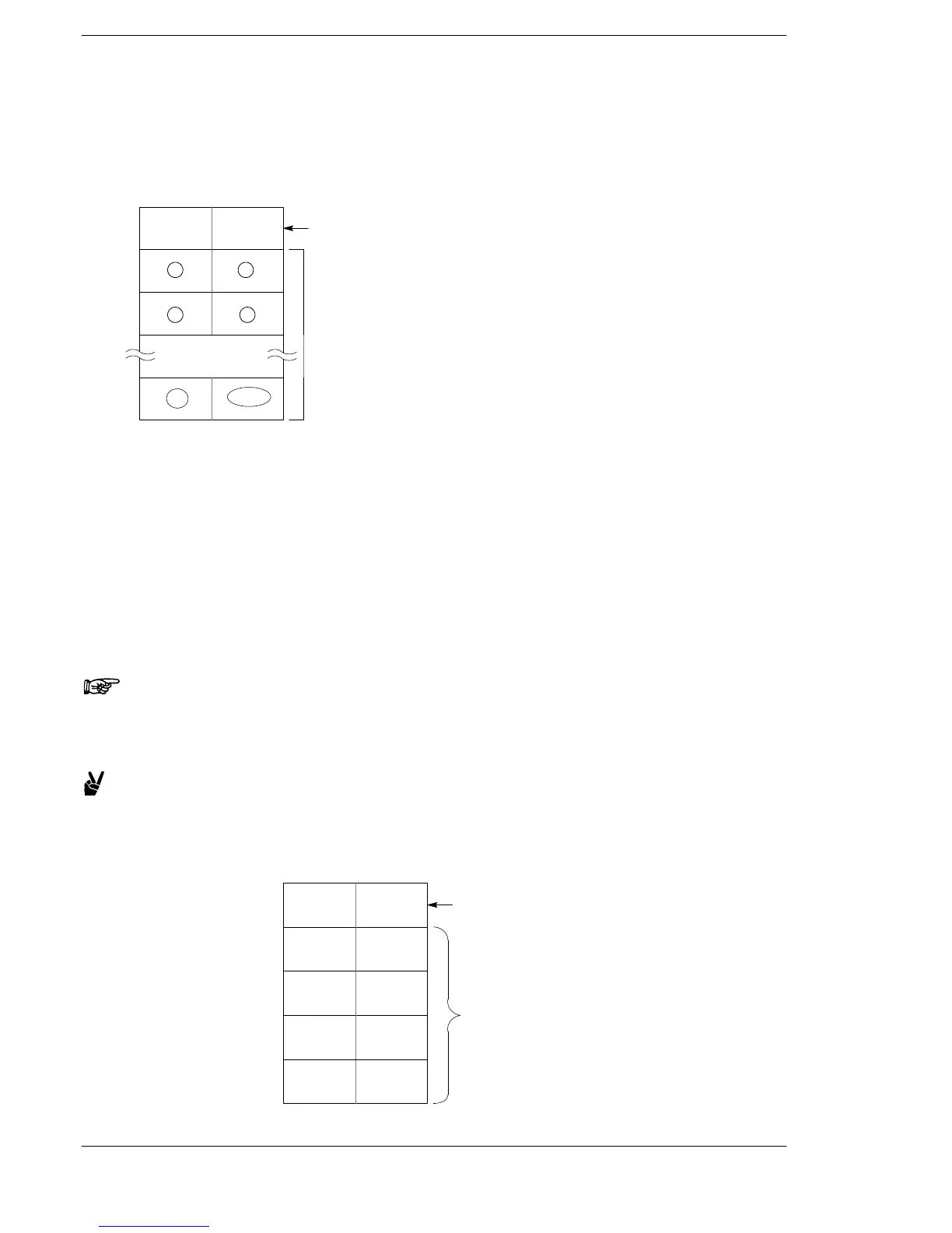
Data table for transmission
Data register areas beginning with the area selected by S are used as the data table for transmission.
[S]
The number of bytes not yet
transmitted is stored here.
[S+1]
[S+2]
[S+n]
12
34
2n
2n−1
Storage area for transmission data
(the circled numbers indicate the
order of transmission).
Write the transmission data to the transmission data storage area selected with S (from the second word on)
using an F0 (MV) or F95 (ASC) instruction.
− Do not include an end code in the transmission data as it will be added automatically.
− If the start code is set to “Yes”, do not include a start code in the transmission data as it will be added
automatically.
− There is no restriction on the number of bytes [n] that can be transmitted. Following the initial area of
the data [S], transmission is possible up to the data range that can be used by the data register.
However, if the FP0R is used as the FP0 (FP0 compatibility mode), the maximum number is 2048
bytes.
When the F144 (TRNS) instruction is executed, the number of data bytes not yet transmitted is stored in the
starting area of the data table. *1
Note
Take care that the transmission data table and reception buffer
areas (set in system registers 417 and 418) do not overlap.
Example:
Transmitting the eight characters A, B, C , D, E, F, G and H (8
bytes of data)
In this example, the data table is DT100 to DT104.
DT100
The number of bytes not yet transmitted is
stored at each transmission. *1
DT101
DT102
DT104
H42(B) H41(A)
H44(D) H43(C)
H48(H) H47(G)
Data is transmitted
in order from the
lower byte.
DT103
H46(F) H45(E)
K8
Data table before transmission
FP0/FP−e












 To Next Page