Boolean
Ladder Diagram
Address Instruction
10
F146 RECV, DT10 , DT 0 , K 100 , DT50
S1
S2
Trigger
R0
N
D
10
11
ST R 0
F146 (RECV)
DT 10
DT 0
K 100
DT 50
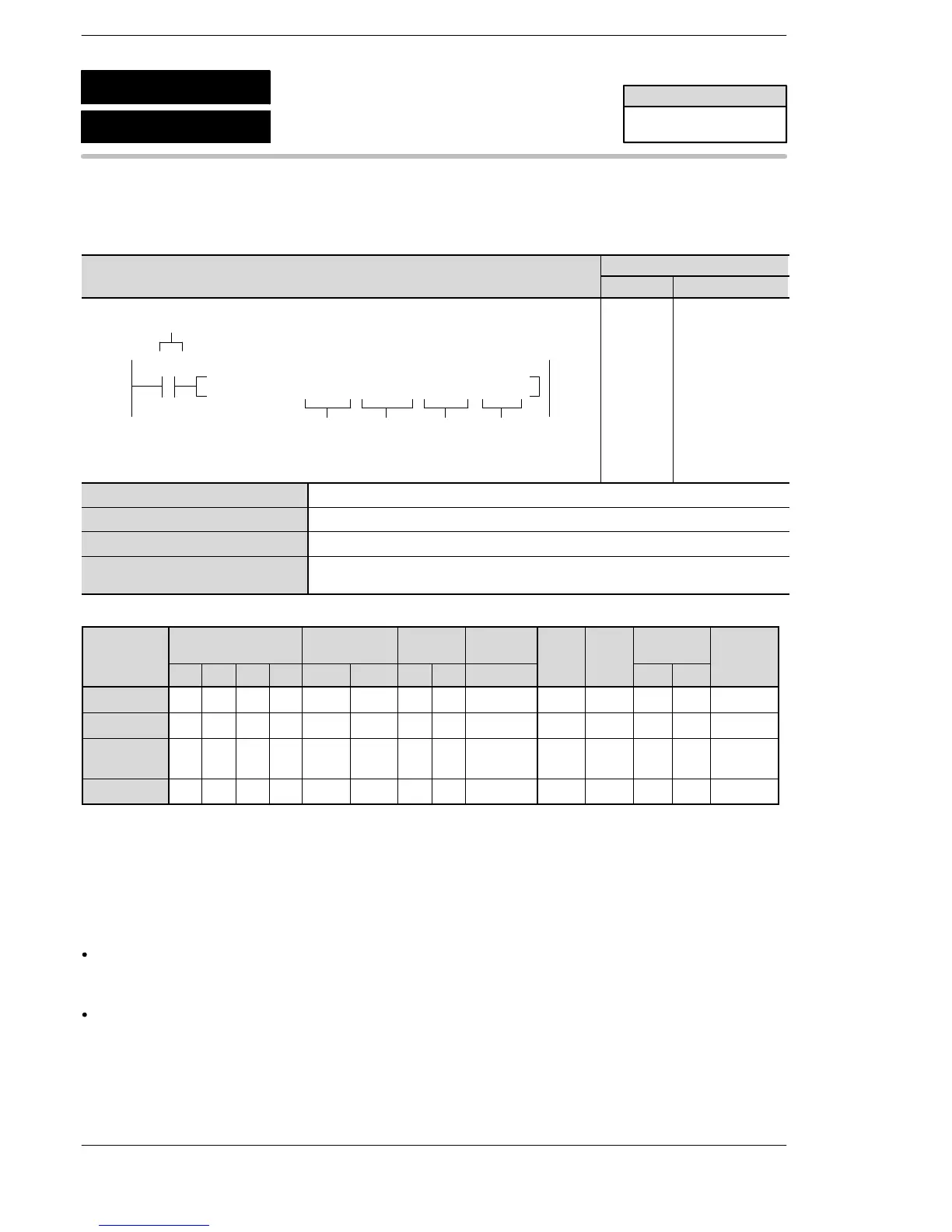
S1 Starting 16-bit area for storing control data
S2 16−bit area of destination to receive (The device No. is fixed at 0).
N Starting address of the destination to receive.
D Starting 16−bit area address for storing data received (destination data area
at local unit).
Operands
O
K H
modifier
S1 A A A A A A A A N/A A A N/A N/A A
S2 A A A A N/A N/A A A N/A N/A N/A N/A N/A N/A
N N/A
A
(*2)
A
(*2)
A
(*2)
A
(*2)
A
(*2)
A
(*2)
A
(*2)
N/A N/A N/A A A A
D N/A A A A A A A A N/A N/A N/A N/A N/A A
(*1) I0 to ID
(*2) It can be specified only for the FP0R, FPΣ V3.20 or later, FP−X V2.50 or later, however, an operation error will occur
not a syntac error if K or H constant is specified as S1 and S2.
Operation
It is used to send commands to the serial port (COM1 or COM2) of the specified unit in the MODBUS
mode connecting the unit that enables to receive the MODBUS command. (MODBUS command 01,
02, 03 and 04)
The data is sent from the area of the remote unit specified by [S2] and [N], and is stored in the area of
the local unit that starts with [D], according to the specification for the 2−word data stored in the control
data that starts with the area specified by [S1].
FPΣ/FP−X/FP0R
F146
P146
(PRECV)
(RECV)
Data receive
(For MODBUS master mode)
Availability
FP0R/FP−X
FPΣ: 32k
A: Available
N/A: Not Available












 To Next Page