High−level Instructions
3 − 376
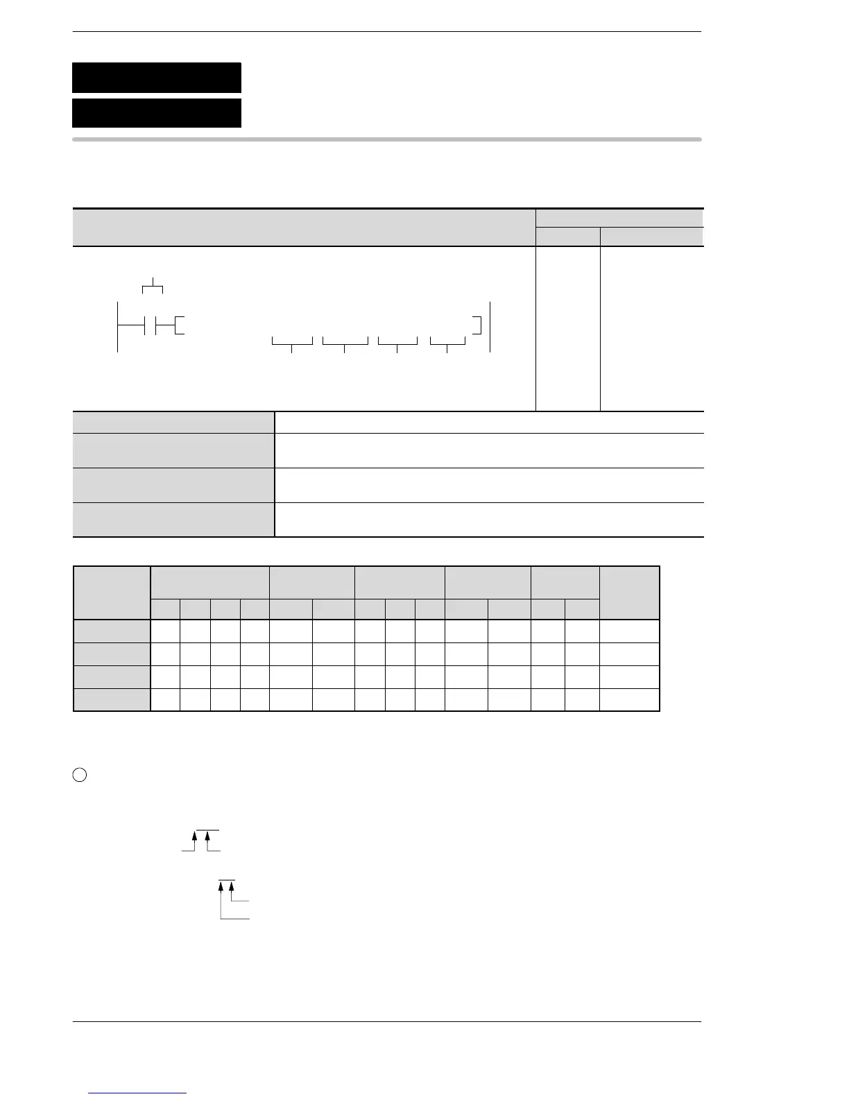
Outline Receives data from another station through link units in the network.
Program example
Boolean
Ladder Diagram
Address Instruction
10
F146 RECV, DT10 , DT 0 , K 100 , DT50
S1
S2
Trigger
R0
N
D
10
11
ST R 0
F146 (RECV)
DT 10
DT 0
K 100
DT 50
S1 Starting 16-bit area for storing control data
S2 Type of source operands for storing data in the remote station. Be sure to
select the area by setting address 0 (source data area at another station).
N Starting 16-bit area address for the source operand specified in S2 above
(source data area at another station).
D Starting 16-bit area address for storing data received (destination data area at
local station).
Operands
O
erand
Relay Timer/Counter Register
Index
register
Constant
Index
WX WY WR WL SV EV DT LD FL IX IY K H
modifier
S1 A A A A A A A A A N/A N/A N/A N/A A
S2 A A A A A A A A A N/A N/A N/A N/A N/A
N N/A N/A N/A N/A N/A N/A N/A N/A N/A N/A N/A A A A
D N/A A A A A A A A A N/A N/A N/A N/A A
Explanation of example
1
Example of word unit reception
When the control data is as follows:
Word unit
5 words
Unit No.10
Route No.1
DT10(S1)=H0005
(=K5)
DT11(S1+1)=H01
0A
the data from DT100 to DT104 of the unit No. 10 connected to route No. 1 is sent to DT50 to DT54 of
the local station when the execution condition (trigger) R0 turns on.
F146
P146
(PRECV)
(RECV)
Data receive (MEWNET link)
A: Available
N/A: Not Available
Phone: 800.894.0412 - Fax: 888.723.4773 - Web: www.clrwtr.com - Email: info@clrwtr.com












 To Next Page