High−level Instructions
3 − 425
Programming and operation during reception
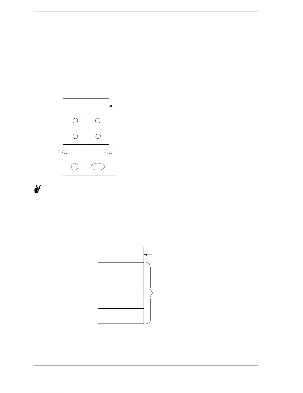
Data sent from an external device connected to the RS232C port is stored in the data registers that have been
set as the reception buffer.
Data registers are used for the reception buffer. Specify the data registers in system registers 416 to 419.
The number of bytes of data received is stored in the starting address of the reception buffer. The initial value
is “0”.
Received data is stored in the received data storage area in order from the lower−order byte.
Word
(address) 0
The number of
bytes received is
stored in this area.
1
2
n
12
2n 2n−1
Reception buffer storage area
(The circled numbers indicate the
order of storage.)
Reception buffer
34
Using a “reception buffer” data register
Example:
Receiving eight bytes of data, A, B, C, D, E, F, G, H, from an
external device through the COM1 port
DT200 to DT204 are used as the reception buffer.
System register settings are as follows:
− System register 416: K200
− System register 417: K5
DT200
The received number of
bytes is stored as data is
stored.
DT201
DT202
DT204
H42
(B)
H41
(A)
H44
(D)
H43
(C)
H48
(H)
H47
(G)
Received data is stored in
order from the lower−order
byte.
DT203
H46
(F)
H45
(E)
K8
Reception buffer when
reception is completed
FPΣ/FP−X/FP0R












 To Next Page