High−level Instructions
3 − 437
Outline This instruction is used to perform control such as software reset,
counter disabling, and high−speed counter instruction clearing.
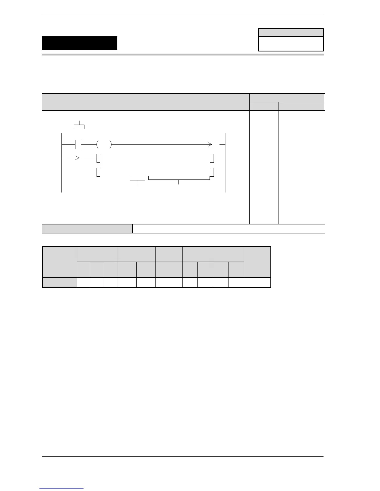
Program example
Boolean
Ladder Diagram
Address Instruction
10
F0 MV , H 1, DT9052 or DT90052
Trigger
R0
1
DF
1
F0 MV , H 0, DT9052 or DT90052
S
High speed counter and
Pulse output
Controls flag area
* The high−speed counter and pulse output controls flag area
varies dependingon the PLC type.
10
11
12
17
ST R 0
DF
F0 (MV)
H1
DT 9052
F0 (MV)
H0
DT 9052
S Area for storing high−speed counter control code or constant data
Operands
Relay Timer/Counter Register
Index
register
Constant
Inde
Operand
WX WY WR SV EV DT
IX
(*1)
IY
(*2)
K H
modifier
S A A A A A A A A A A A
(*1) I0 to IC on FPΣ/FP−X/FP0R
(*2) ID on FPΣ/FP−X/FP0R
Description
Performs high−speed counter control according to the control code specified in “S”.
This instruction is used to perform the following operations when using a high−speed counter:
<Function>
1) Performing a software reset
2) Disabling the count
3) Temporarily disables reset input setting using external inputs
4) Clearing control executed with high−speed counter and pulse output instructions F166 or F167.
Once written, a control code is retained until the next write operation.
Precautions during programming
Hardware resets can only be disabled if a reset input is used.
FP0/FPΣ/FP−X/FP0R
High−speed counter control
F0
(MV)
Availability
FP0/FP0R/FPΣ/FP−X
A: Available
Phone: 800.894.0412 - Fax: 888.723.4773 - Web: www.clrwtr.com - Email: info@clrwtr.com












 To Next Page