High−level Instructions
3 − 438
Flag conditions
・Error flag (R9007): Turns on and stays on when:
・Error flag (R9008): Turns on for an instant when:
− The area is exceeded when an index modifier is used
− The “S” is outside specification range
Using the FP0/FP−e
High−speed counter and Pulse output controls flag area
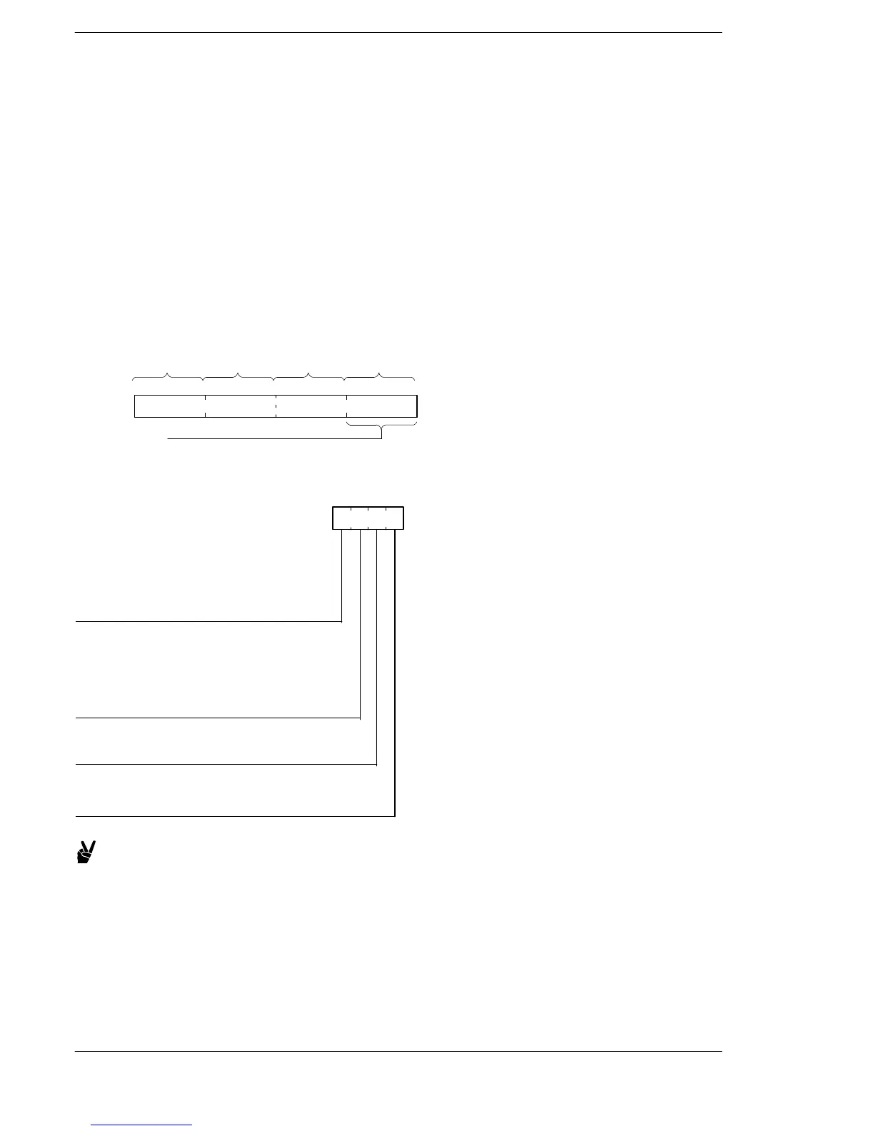
Four bits are allocated to each high−speed counter channel for use as the control code write area DT9052
(DT90052 on the FP0 T32)
A control code written using an F0(MV) instruction is stored in special data register DT9052 (DT90052 on the
FP0 T32).
High−speed counter and Pulse output controls flag area of FP0
DT9052:
DT90052:
15 12 11 8 7 4 3 0
ch3 ch2 ch1 ch0
<Control code>
Written using an F0(MV)
instruction (H0 to HF)
Select control codes in units of one bit and specify with H.
H
Clears high−speed counter instruction
0: Continue
1: Clear
Count
0: Permit
1: Prohibit
Software reset
0: No
1: Yes
Note:
At the reset input setting, you set
whether the reset input (X2 or X5),
which was assigned by the system
register high−speed counter setting,
will be enabled or disabled.
Reset input setting (See note.)
0: Enable
1: Disable
Example:
・Perform software reset H1(0001).......................
・Prohibit count H2(0010)...............................
・Clear high− speed counter instruction H8(1000).........
・Clear high −speed counter instruction and reset
elapsed value H9(1001)...............................
FP0/FPΣ/FP−X/FP0R












 To Next Page