High−level Instructions
3 − 440
Program example
Example 1: Software reset of channel 0 of high−speed counter
R0
DF F0 MV, H1, DT90052
F0 MV, H0, DT90052
Example 2: Software reset of channel 2 of high−speed counter
F0 MV, H2001, DT90052
F0 MV, H2000, DT90052
R0
DF
Using the FP−X
High−speed counter and Pulse output controls flag area
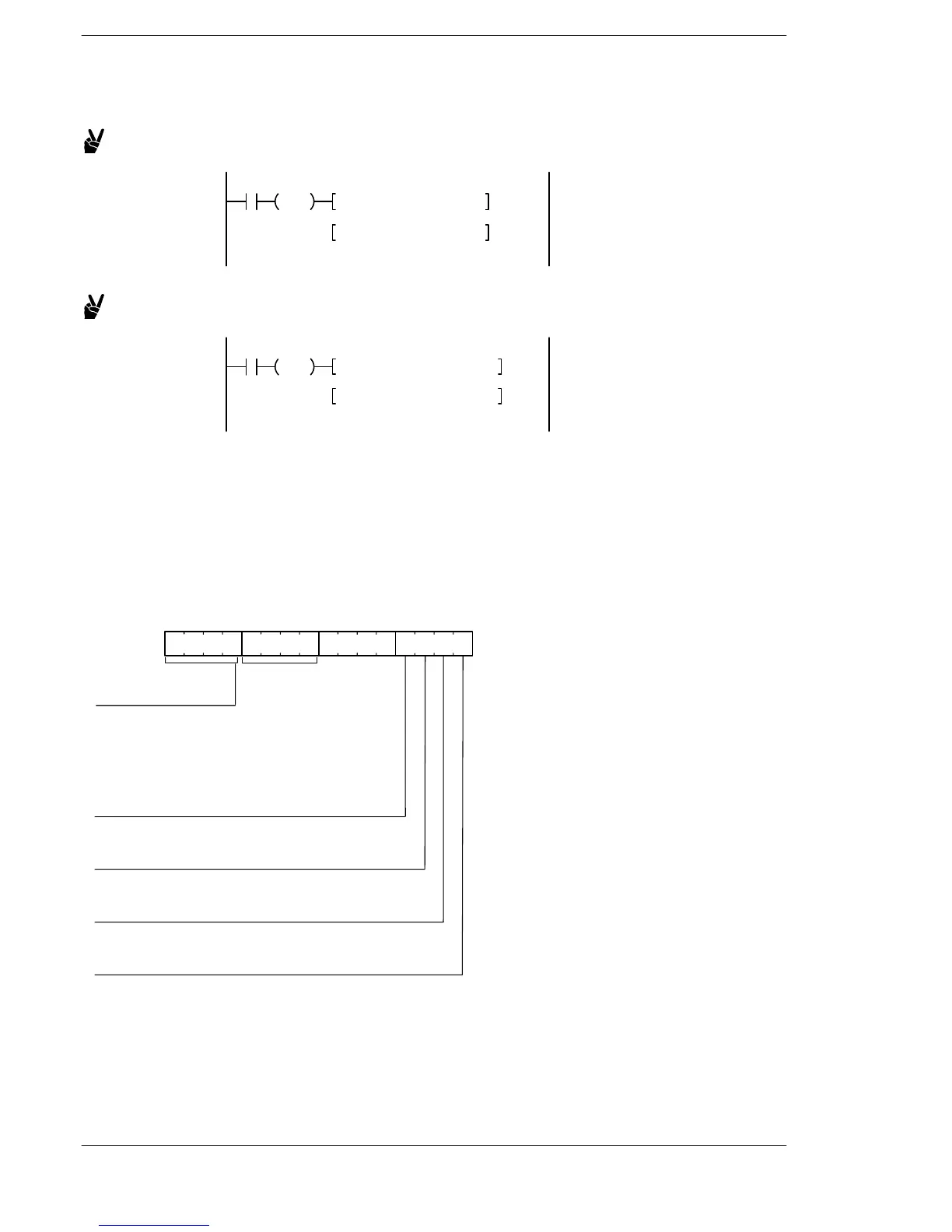
The area DT90052 for writing channels and control codes is allocated as shown below.
The control code written by the F0 (MV) instruction is stored in the control code monitor area while it is written
in the special register DT90052. (Refer to the table below.)
The written data is the data for lower 8 bits only.
High−speed counter and Pulse output controls flag area of FP−X
15 12 11 8 7 4 3 0
Clear high−speed counter instruction
0: Continue
1: Clear
Count
0: Permit
1: Prohibit
Software reset
0: No
1: Yes
DT90052:
Channel specification
H0 to HB: CH0 to CHB
H0 fixation
(HSC)
Reset input setting (See note.)
0: Enable
1: Disable
However, the settable channels differ
depending on the models.
(Refer to the table on the next page.)
FP0/FPΣ/FP−X/FP0R












 To Next Page