High−level Instructions
3 − 444
Flag conditions
・Error flag (R9007): Turns on and stays on when:
・Error flag (R9008): Turns on for an instant when:
− The area is exceeded when an index modifier is used
− The “S” is outside specification range
Using the FP0/FP−e
High−speed counter and Pulse output controls flag area
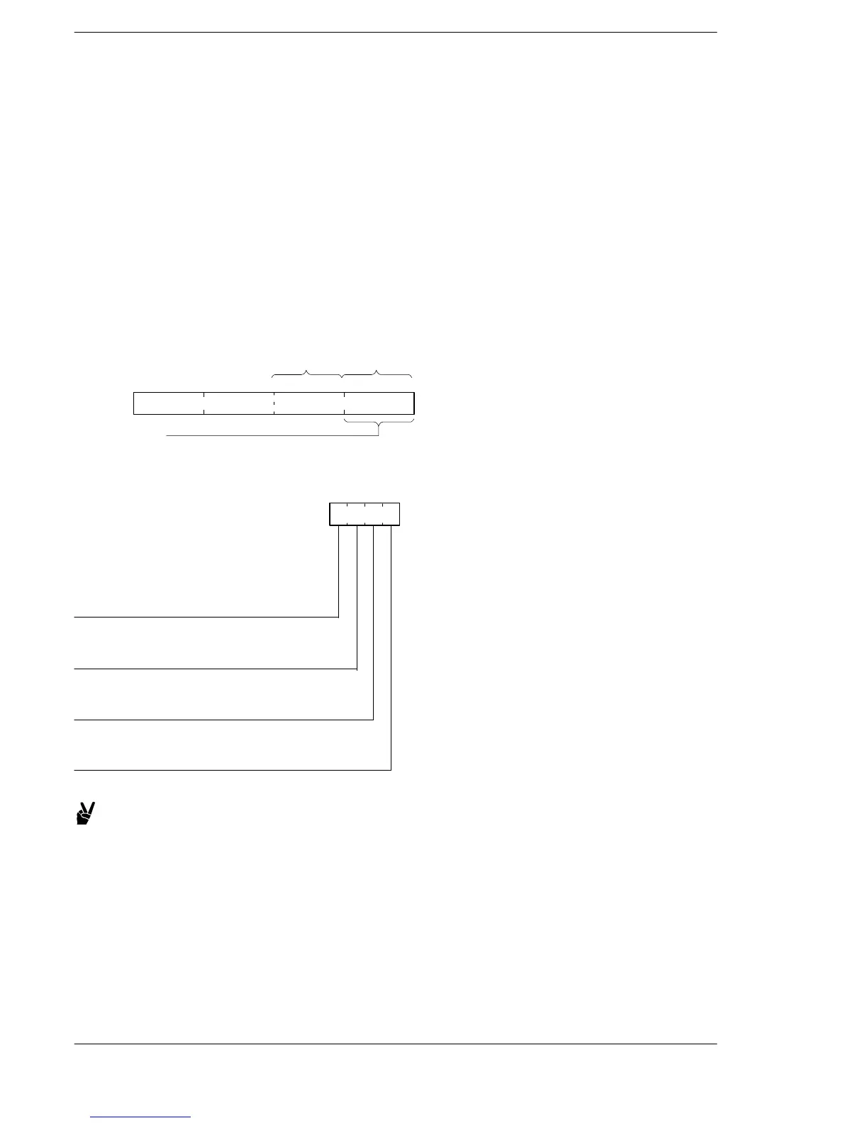
Four bits are allocated to each Pulse output channel for use as the control code write area DT9052 (DT90052
on the FP0 T32)
A control code written using an F0(MV) instruction is stored in special data register DT9052 (DT90052 on the
FP0 T32).
High−speed counter and Pulse output controls flag area of FP0
DT9052:
DT90052:
15 12 11 8 7 4 3 0
ch1 ch0
<Control code>
Written using an F0(MV)
instruction (H0 to HF)
Select control codes in units of one bit and specify with H.
H
Stop pulse output
0: Continue
1: Stop
Count
0: Permit
1: Prohibit
Near home input
0: Enable
1: Disable
Software reset
0: No
1: Yes
Example:
・Perform software reset H1(0001).......................
・Prohibit count H2(0010)...............................
・Stop pulse output H8(1000)............................
・Turn off pulse output and reset elapsed value H9(1001)..
FP0/FP−e/FPΣ/FP−X/FP0R












 To Next Page