High−level Instructions
3 − 449
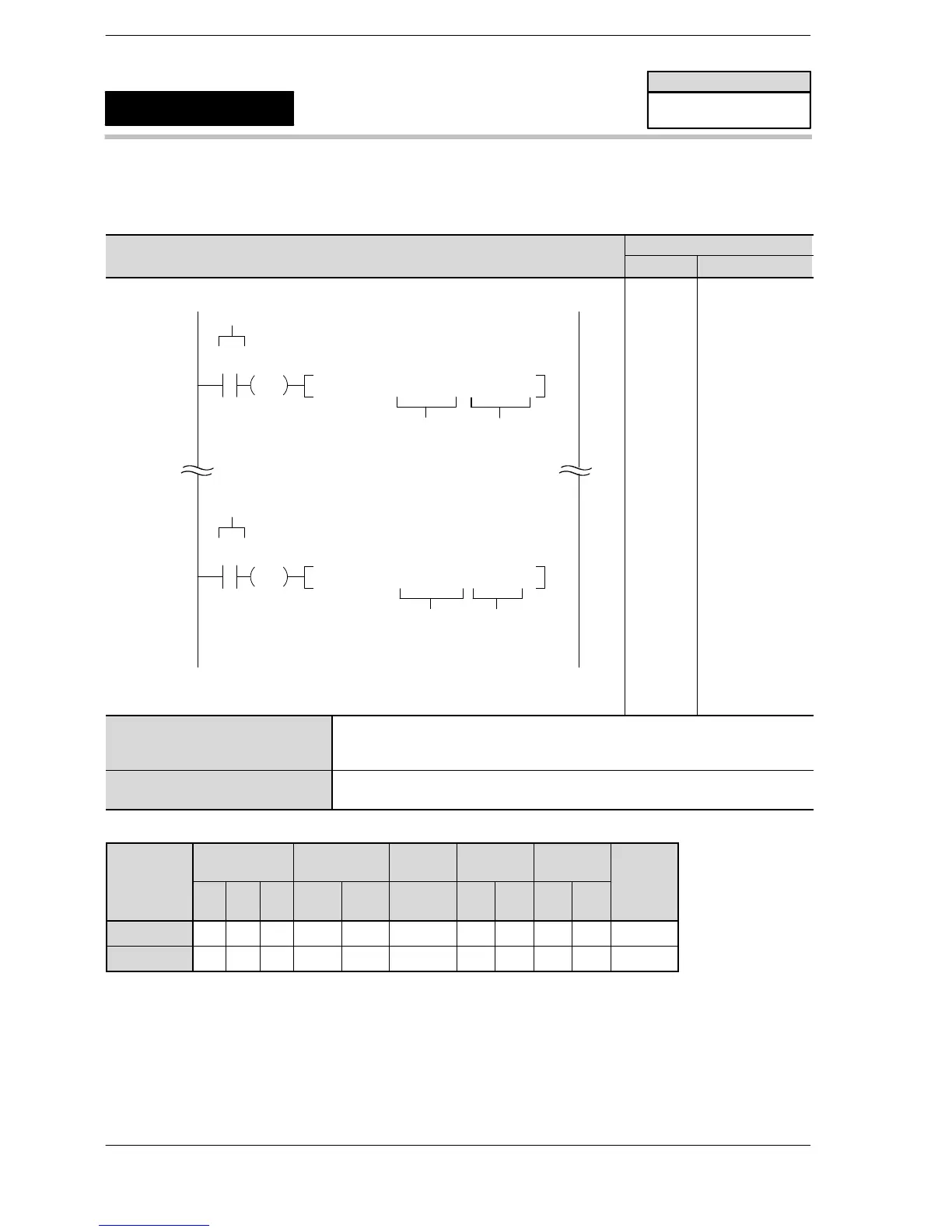
Outline This instruction is used to write and read the elapsed value of the
high−speed counter/pulse output.
Program example
Boolean
Ladder Diagram
Address Instruction
10
F1 DMV , K 3000 , DT9044
S
Elapsed value area
of high−speed
counter and
pulse output
Trigger
R0
DF
20
F1 DMV , DT9044 , DT 6
Trigger
R10
DF
D
Elapsed value area of
high−speed counter and
pulse output
Writing
Reading
* The high−speed counter and pulse output elapsed value area
varies dependinon the PLC type.
10
11
12
:
:
20
21
22
ST R 0
DF
F1 (DMV)
K 3000
DT 9044
:
:
ST R 10
DF
F1 (DMV)
DT 9044
DT 6
S W r iting
Area for storing the elapsed value (32 bits) write in the high−speed
counter/pulse output, or constant data
D Reading
Area for reading the elapsed value of the high−speed counter/pulse output
Operands
Relay Timer/Counter Register
Index
register
Constant
Inde
Operand
WX WY WR SV EV DT
IX
(*1)
IY
(*2)
K H
modifier
S A A A A A A A N/A A A A
D N/A A A A A A A N/A N/A N/A A
(*1) I0 to IC on FPΣ/FP−X/FP0R
(*2) ID on FPΣ/FP−X/FP0R
FP0/FP−e/FPΣ/FP−X/FP0R
Writing and reading the high−speed
counter and pulse output elapsed
value
F1
(DMV)
Availability
FP0/FP0R/FP−e/
FPΣ/FP−X
A: Available
N/A: Not Available
Phone: 800.894.0412 - Fax: 888.723.4773 - Web: www.clrwtr.com - Email: info@clrwtr.com












 To Next Page