High−level Instructions
3 − 448
Example 2: Enable near home input during pulse output control and change
to deceleration.
X3
DF F0 MV, H110, DT90052
F0 MV, H100, DT90052
(ch0)
X3
DF F0 MV, H1110, DT90052
F0 MV, H1100, DT90052
(ch1)
Using the FP0R
High−speed counter and Pulse output controls flag area
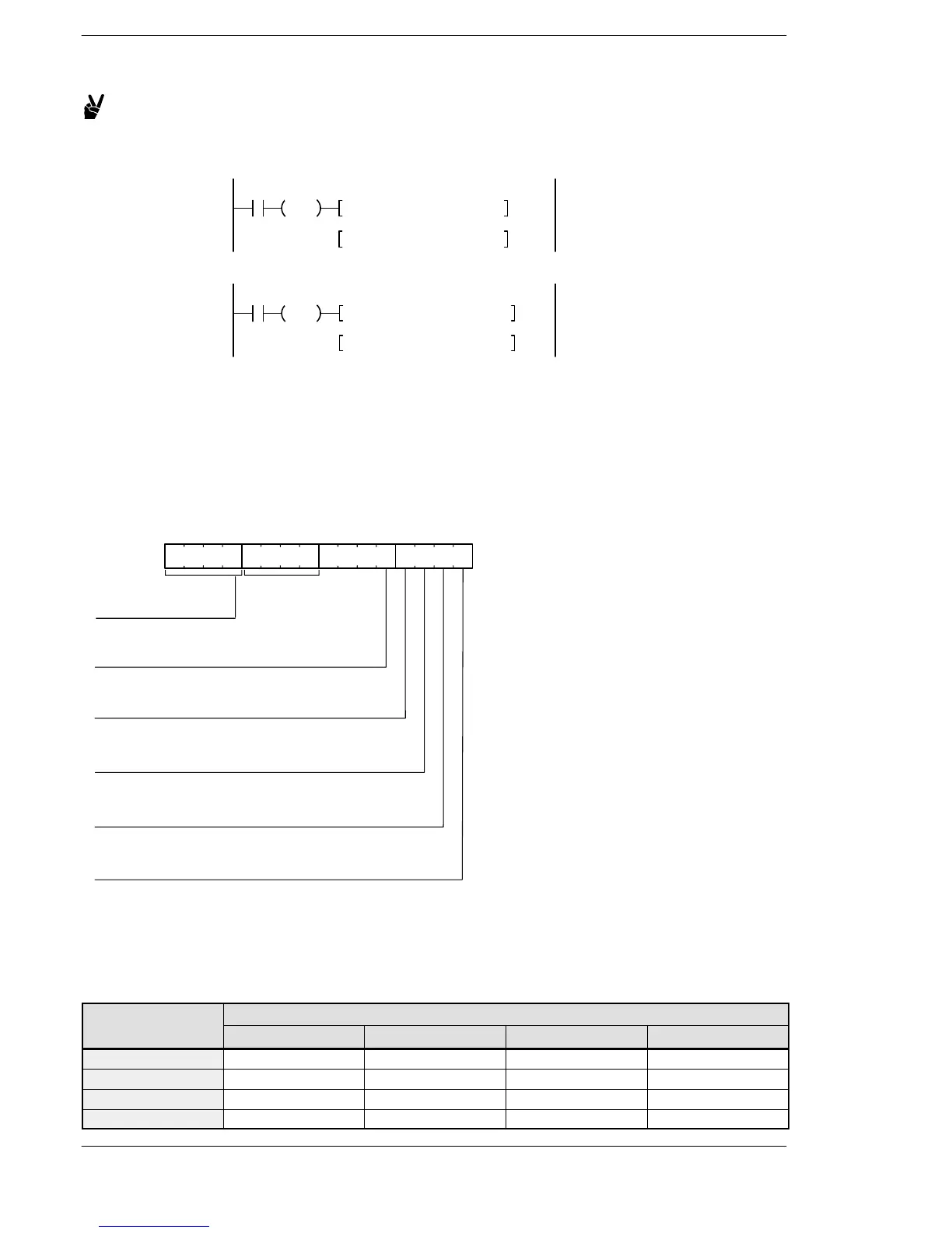
The area DT90052 for writing channels and control codes is allocated as shown below.
The control code written by the F0 (MV) instruction is stored in the control code monitor area while it is written
in the special register DT90052. (Refer to the table below.)
The written data is the data for lower 8 bits only.
High−speed counter and Pulse output controls flag area of FP0R
15 12 11 8 7 4 3 0
Near home input
0: Enable
1: Disable
Stop pulse output
0: Continue
1: Stop
Count
0: Permit
1: Prohibit
Software reset
0: No
1: Yes
DT90052:
Channel specification
H0 to H3: CH0 to CH3
H1 fixation
(PLS)
Clear of pulse output control
0: Continue,
1: Stop
* The pulse output control is available when controlling the pulse
output ch with F166(HC1S) or F167(HC1R) instruction.
Program example
Refer to the program example of FP−X.
Pulse output control for FPΣ and FP−X
Channel No.
Control code monitor area
FPΣ FP−X Ry type FP−X Tr type FP0R
ch0 DT90190 DT90372 DT90380 DT90380
ch1 — DT90373 DT90381 DT90381
ch2 DT90192 — DT90382 DT90382
ch3 — — DT90383 DT90383
FP0/FP−e/FPΣ/FP−X/FP0R












 To Next Page