1.3 Explanation of Memory Areas
1-49
1.3.4 WX, WY, WR and WL
Function of WX, WY, WR and WL
Relays (X, Y, R, L) can be handled as blocks of 16 points.
These are one−word (16−bit) memory areas, thus they can be treated as data memory.
The composition of the one−word memory areas is as follows.
The numbers correspond to the words as shown.
WR0
WR1
WR2
RF RE RD RC RB RA R9 R8 R7 R6 R5 R4 R3 R2 R1 R0
R1F R1E
·
R12 R11 R10
··········
R2F R2E
·
R22 R21 R20
··········
For the FP2/FP2SH/FP10SH, if the Initialize/Test switch is set to the upper side (the
Initialize side) in the PROG mode, WX, WY, WR, and WL are cleared to 0. Even if a hold
type has been specified, these are cleared to 0.
Pulse relays (P) and error alarm relays (E) cannot be handled in word units.
Examples of using WX, WY, WR and WL
WX can be used to read in digital switch and keyboard inputs, and WY can be used for
output to 7−segment displays.
WR can also be used as a shift register.
All of the relays can be used to monitor 16−bit words.
Precautions concerning usage
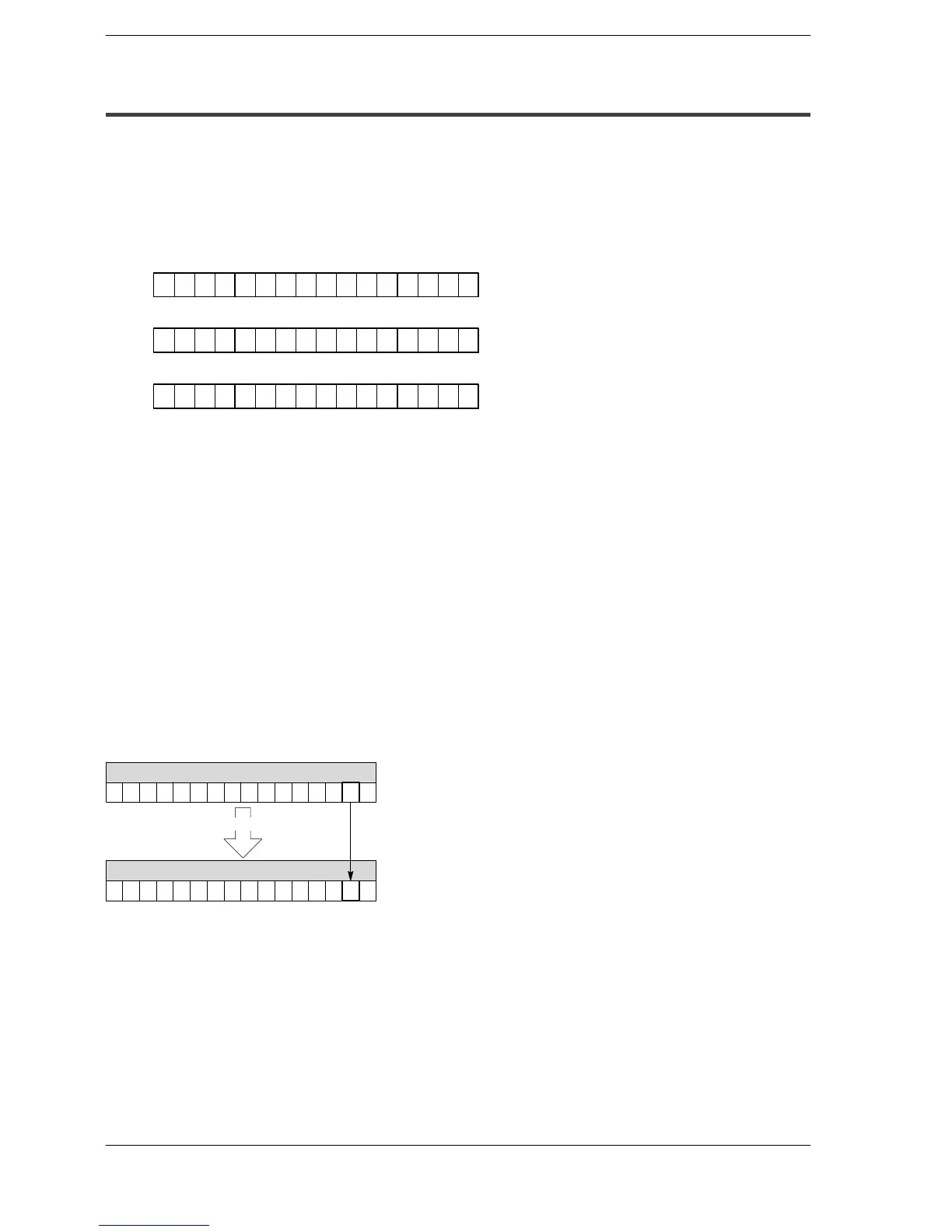
If an on or off status of one of the relays composing the memory area changes, the
memory area value will also change.
0000000000001001
WR0
0000000000001011
WR0
When R1 is turned on
(H9)
(HB)
 Loading...


