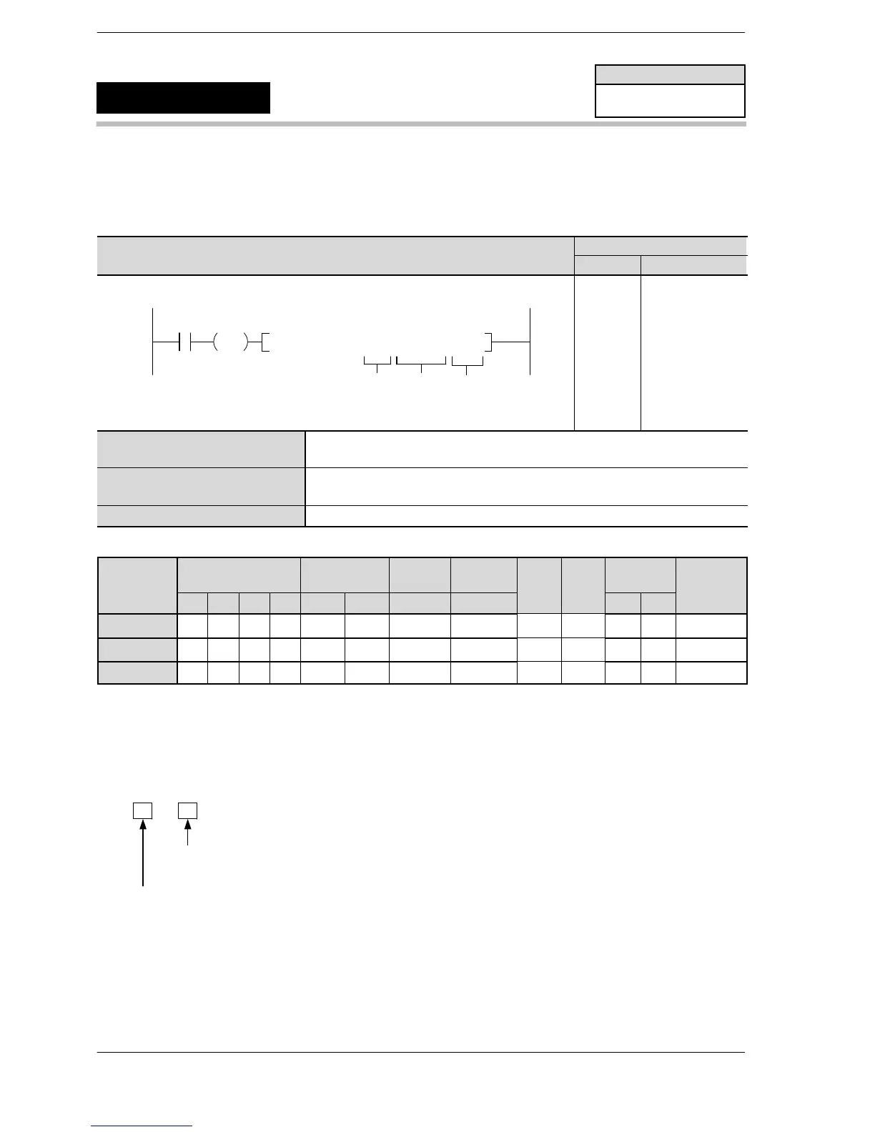
High−level Instructions
3 − 473
Outline When the elapsed value of the specified channel of the high−speed
counter (HSC) matches the target value, the specified output is turned
off.
Program example
Boolean
Ladder Diagram
Address Instruction
DF
F167 HS1R , H0, K10000, Y2
R0
D
Sn
10
11
12
ST R 0
DF
F167 (HC1R)
H0
K 10000
Y2
n
The channel number of the high−speed counter that corresponds to the match
output.
S
The high−speed counter target value data or the starting address of the area
that contains the data.
D The output coil that is turned on when the values match. (Yn)
Operands
O
K H
modifier
n N/A N/A N/A N/A N/A N/A N/A N/A N/A N/A A A N/A
S A A A A A A A A N/A N/A A A A
D N/A N/A N/A N/A N/A N/A N/A N/A N/A N/A N/A N/A N/A
(*1) I0 to ID
Description
The number specified in “S” is set as the target value of the high−speed counter, and when the elapsed value
matches the target value, the specified output “Yn” turns off (by interrupt processing).
Specify the channel number of the high−speed counter in “n”.
H0 0 0 0
<Specification of the channel of high−speed counter/pulse output>
Allowable range for specifying the high−speed counter: 0 to 5
<Specification of high−speed counter/pulse output>
0: Specification of high−speed counter
The target value setting and target value match output control are cleared when the elapsed value matches
the target value.
Specify a 32−bit data value for the target value “S” within the following range:
FP0R K−2,147,483,648 to K2,147,483,647
The “S” value is stored in the target value area when the instruction is executed.
FP0R
Target value match off
(High−speed counter control)
F167
(HC1R)
Availability
FP0R
A: Available
N/A: Not Available












 To Next Page