WX WY WR SV EV DT IX IY K H
modifier
S N/A N/A N/A N/A N/A A N/A N/A N/A N/A A
n N/A N/A N/A N/A N/A N/A N/A N/A A A N/A
Description
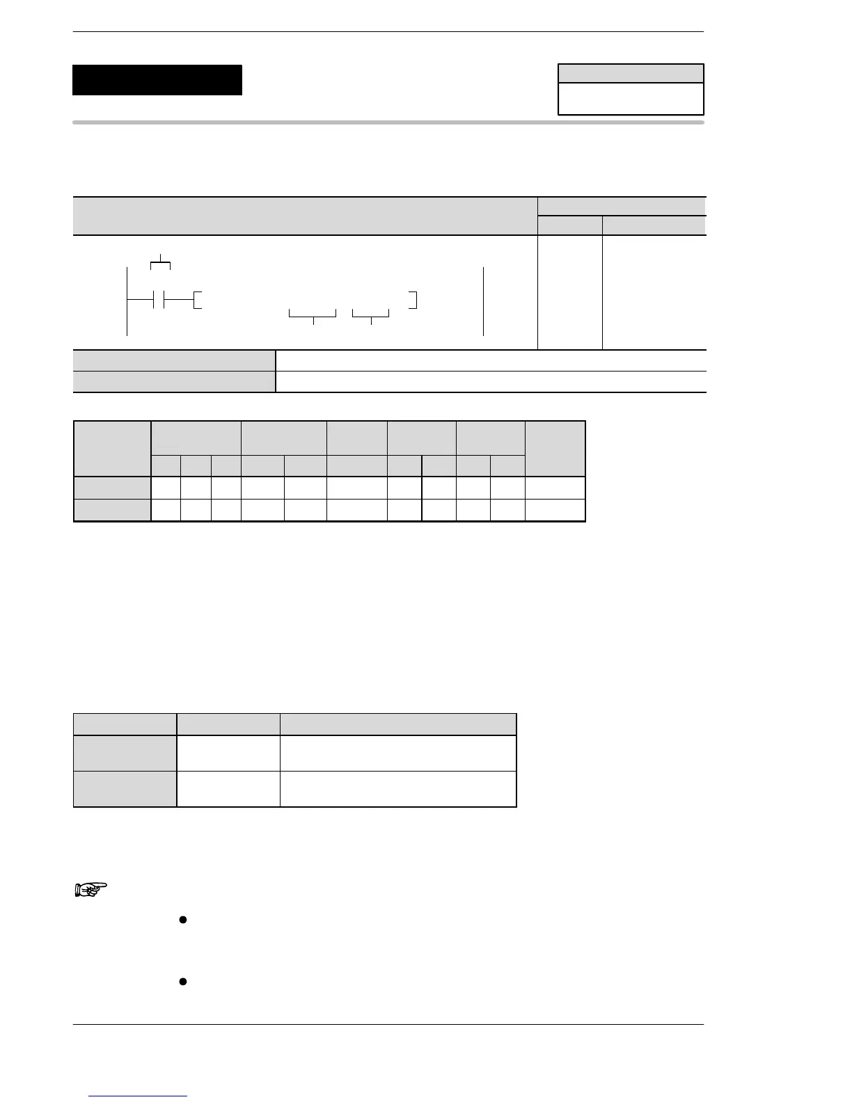
When the corresponding control flag is off and the execution condition (trigger) is in the on state, a pulse is
output from the specified channel. The pulse is output while the execution condition (trigger) is in the on state.
By specifying either incremental counting or decremental counting in the control code, this instruction can be
used as an instruction for JOG operations. For that situation, set the control code with combinations such as
H12 (incremental, directional output off) and H22 (decremental, directional output on).
The frequency and duty can be changed each scan. (This becomes effective with the next pulse output after
this instruction is executed.)
See below for the corresponding areas.
Channel no. Control flag Data register for elapsed value
ch0 R903A
DT9044, DT9045
(For FP0 T32, DT90044, DT90045)
ch1 R903B
DT9048, DT9049
(For FP0 T32, DT90048, DT90049)
When using the incremental counting mode, the pulse stops when the elapsed value exceeds H7FFFFF.
When using the decremental counting mode, the pulse stops when the elapsed value exceeds HFF800000.
Notes
When this instruction is used, the setting for the channel
corresponding to system register 400 should be set to
“High−speed counter not used”.
By performing a rewrite during RUN while operating, the pulse
output will stop during rewriting.
FP0/FP−e
Pulse output
(with channel specification)
(JOG operation)
5
F169
(PLS)
Availability
FP0/FP−e
A: Available
N/A: Not Available












 To Next Page