High−level Instructions
3 − 498
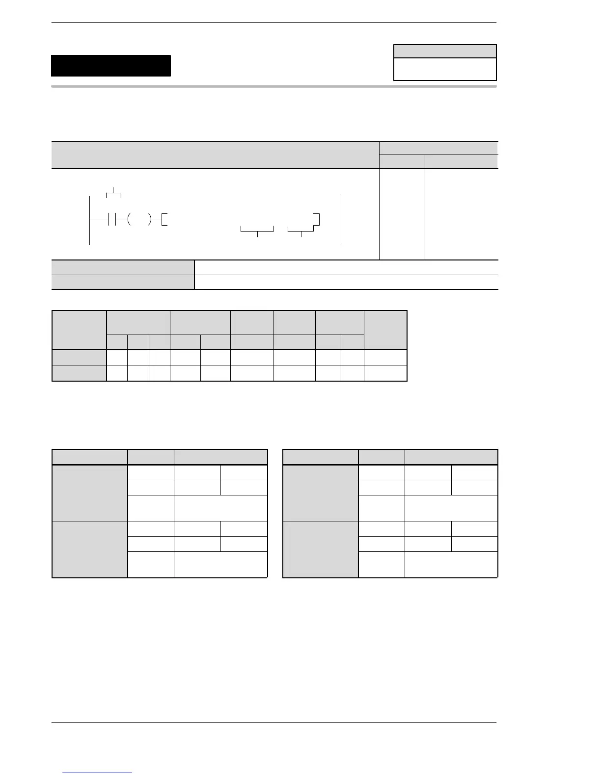
Outline This instruction outputs pulses from the specified channel for the pulse
output according to the specified parameters.
Program example
Boolean
Ladder Diagram
Address Instruction
10
F171 SPDH , DT100 , K 2
S
n
Trigger
R10
DF
10
11
12
ST R 10
DF
F171 (SPDH)
DT 100
K2
S Starting address of area containing the data table.
n Channel for pulse output.
Operands
O
erand
Relay Timer/Counter Register
Index
register
Constant
Index
WX WY WR SV EV DT I K H
modifier
S N/A N/A N/A N/A N/A A N/A N/A N/A A
n N/A N/A N/A N/A N/A N/A N/A A A N/A
Description
Pulses are output from the specified channel when the corresponding control flag turns off and the excution
condition is in on state.
For FP Σ For FP−X Ry type (AFPX−PLS)
Channel no. Output Output method Channel no. Output Output method
ch0 Y0 CW PLS ch0
Y100 CW PLS
Y1 CCW SIGN
Cassete
mounting part 1
Y101 CCW SIGN
Y2 Deviation counter
clear
Y102 Deviation counter
clear
ch2 Y3 CW PLS ch1
Y200 CW PLS
Y4 CCW SIGN
Cassete
mounting part 2
Y201 CCW SIGN
Y5 Deviation counter
clear
Y202 Deviation counter
clear
FPΣ/FP−X
Pulse output
(with channel specification)
(home position return)
5
F171
(SPDH)
Availability
FPΣ/FP−X
A: Available
N/A: Not Available
Phone: 800.894.0412 - Fax: 888.723.4773 - Web: www.clrwtr.com - Email: info@clrwtr.com












 To Next Page