High−level Instructions
3 − 521
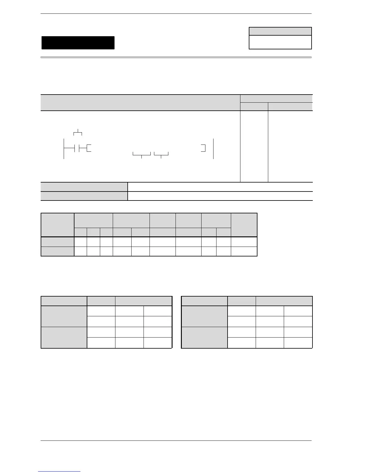
Outline Outputs the pulses of the specified parameter from the specified
channel for the pulse output.
Program example
Boolean
Ladder Diagram
Address Instruction
10
F172 PLSH, DT 10, K 0
S
n
Trigger
R10
10
11
ST R 10
F172 (PLSH)
DT 10
K0
S Starting number for the area that contains the data table
n Channel that corresponds to the pulse output
Operands
O
erand
Relay Timer/Counter Register
Index
register
Constant
Index
WX WY WR SV EV DT I K H
modifier
S N/A N/A N/A N/A N/A A N/A N/A N/A A
n N/A N/A N/A N/A N/A N/A N/A A A N/A
Description
When the corresponding control flag is off and the execution condition is in the on state, pulses are output
from the specified channel. The pulses are output while the execution condition is on.
For FP Σ For FP−X Ry type (AFPX−PLS)
Channel no. Output Output method Channel no. Output Output method
ch0 Y0 CW PLS ch0
e
mounting part 1
Y101 CCW SIGN
ch2 Y3 CW PLS ch1
e
mounting part 2
Y201 CCW SIGN
FPΣ/FP−X
F172
(PLSH)
Pulse output
(with channel specification)
(JOG operation)
Availability
FPΣ/FP−X
A: Available
N/A: Not Available
Phone: 800.894.0412 - Fax: 888.723.4773 - Web: www.clrwtr.com - Email: info@clrwtr.com












 To Next Page