High−level Instructions
3 − 522
For FP−X Tr type
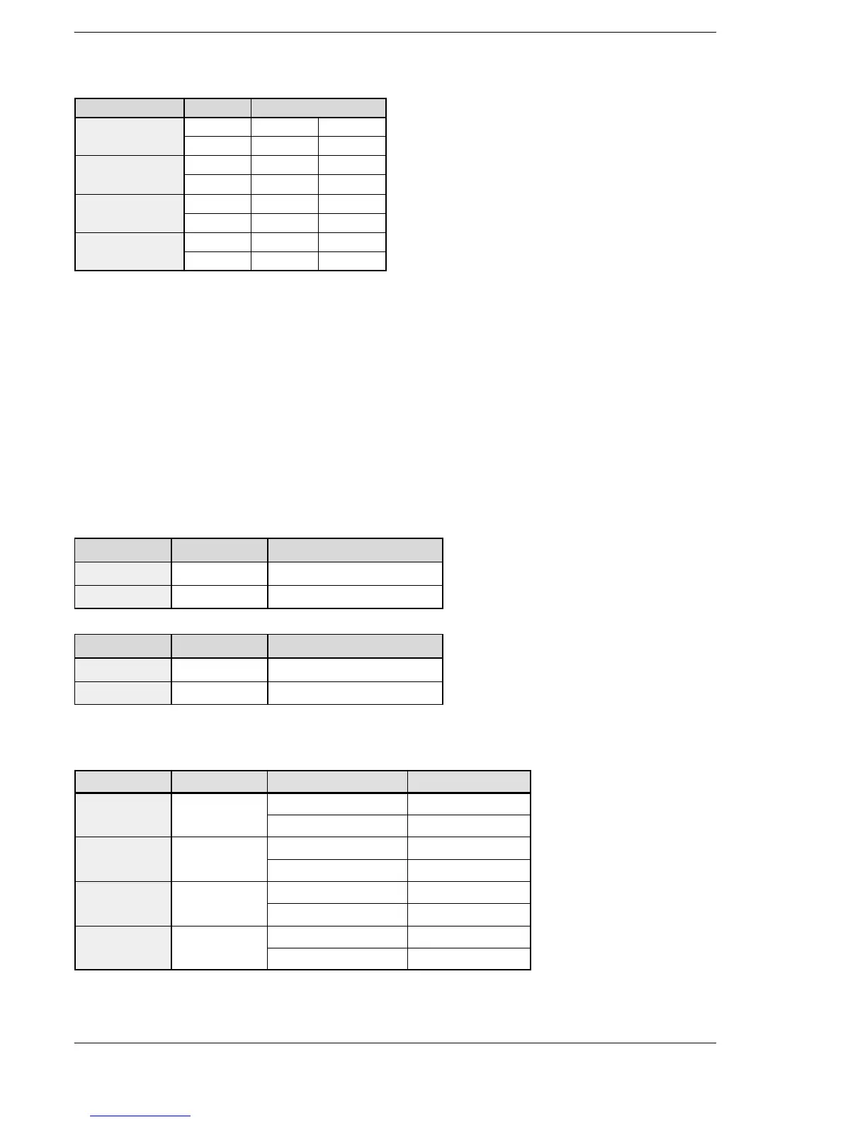
Channel no. Output Output method
ch0 Y0 CW PLS
Y1 CCW SIGN
ch1 Y2 CW PLS
Y3 CCW SIGN
ch2 Y4 CW PLS
Y5 CCW SIGN
ch3 Y6 CW PLS
Y7 CCW SIGN
Note) There is no ch3 for C14T and C14TD.
Note) The pulse I/O cassette (AFPX−PLS) cannot be installed on the FP −X Tr type.
Note) Use the ch2 and ch3 at up to 20 kHz.
By specifying either addition counting or subtraction counting in the control code, this instruction can be used
as an instruction for JOG operations.
Frequency can be changed in each scan, and the target value can be changed asynchronously. However,
the control code cannot be changed during instruction execution.
If a frequency of 50 kHz or higher is specified, a duty of 1/4 (25%) should be specified.
If the frequency for ch2 or ch3 of FP−X Tr type is set to 10kHz or more, specify a duty of 1/4 (25%).
Table of areas used
For FP Σ
Channel no. Control flag Elapsed value
ch0 R903A DT90044, DT90045
ch2 R903C DT90200, DT90201
For FP−X Ry type
Channel no. Control flag Elapsed value
ch0 R911C DT90348, DT90349
ch1 R911D DT90352, DT90353
Note) Ch1 cannot be used for C14R.
For FP−X Tr type
Channel no. Control flag Elapsed value area Target value area
DT90361 DT90363
Note) There is no ch3 for C14T and C14TD.
Note) The pulse I/O cassette (AFPX−PLS) cannot be installed on the FP −X Tr type.
Note) Use the ch2 and ch3 at up to 20 kHz.
FPΣ/FP−X





 To Next Page