1.3 Explanation of Memory Areas
1-55
Example:
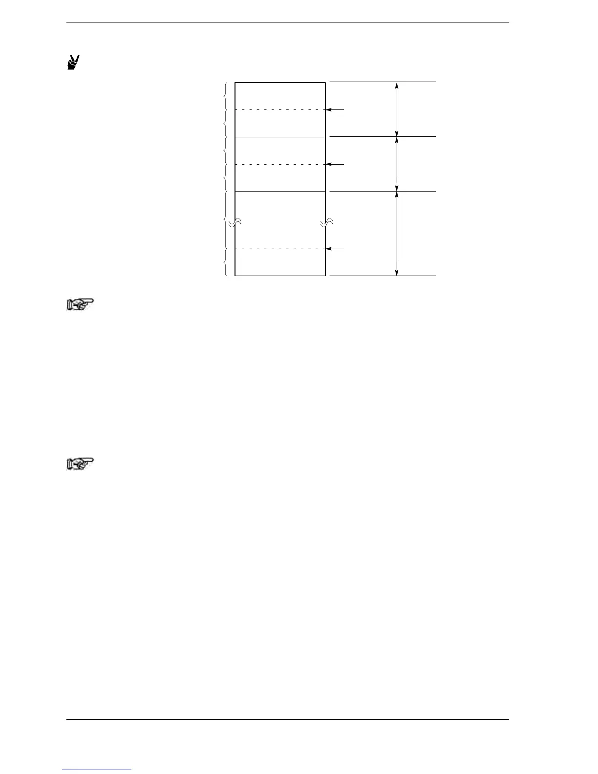
Non−hold type
Hold type
Non−hold type
Hold type
System
register 12
System
register 13
LD0
to
LD127
LD128
to
LD255
Non−hold type
Hold type
System
register 17
LD256
to
LD8447
Note
Link data registers must be allocated when the network is
configured, before programming is done. The method by which
allocations are made varies depending on the type of network.
Refer to the manual for the pertinent link unit.
For the FP2/FP2SH/FP10SH, if the Initialize/Test switch is set to the upper side (the
Initialize side) in the PROG mode, all of the link data registers (LD) are cleared to 0.
Even if a hold type has been specified, these link data registers are cleared to 0.
Note
With the FP2SH/FP10SH, system register 4 can be set in such a
way that the link data registers are not cleared to 0 even if the
Initialize/Test switch is set to the upper side.
 Loading...


