High−level Instructions
3 − 538
Outline Outputs pulses from the specified pulse output channels according to
the specified data table.
Program example
WX WY WR SV EV DT I K H
modifier
S N/A N/A N/A N/A N/A A N/A N/A N/A A
n N/A N/A N/A N/A N/A N/A N/A A A N/A
Description
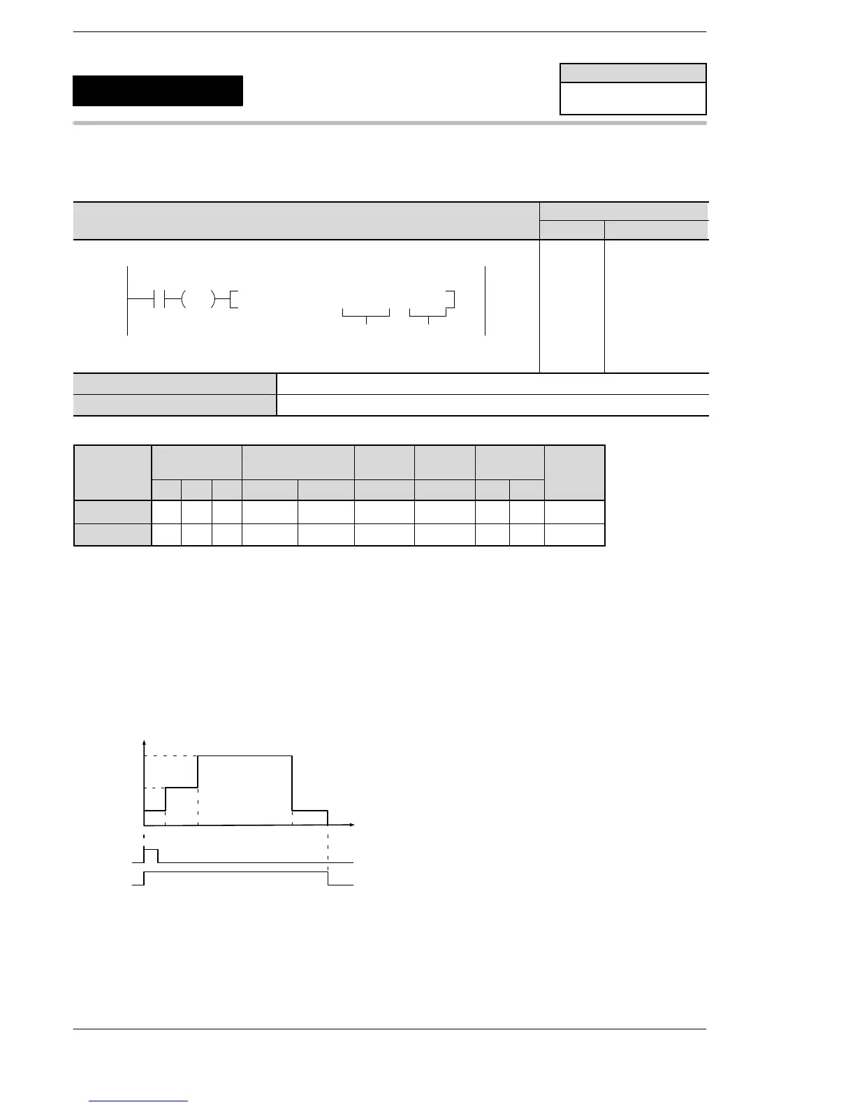
When the corresponding pulse output instruction flag is off and the trigger is on, pulses are output from the
specified channels according to the conditions specified in the data table which starts with the address
specified by [S].
If the elapsed value of the pulse output reaches the target value specified in the data table, the pulse
frequency is changed (by the inerrupt operation).
When the elapsed value reaches the final target value, the pulse output stops.
Image of operation
0 1000 3000 8000 10000
1000
2500
5000
High−speed
couonter
Elapsed value
(Moving distance)
Flag
R10
Pulse output
instruction
flag
R9120
Frequency (speed) [Hz]
FP0R
Pulse output (Arbitrary data
table control operation)
5
F174
(SP0H)
Availability
FP0R
A: Available
N/A: Not Available












 To Next Page