High−level Instructions
3 − 540
*1: Assignment of control code (Specify with H constant)
H
10: Fixed
Control assignment
0: Arbitrary table control
Operation mode assignment
0: Incremental
1: Absolute
Output type assignment
0: CW/CCW
1: PLS+SIGN (Forward OFF/Reverse ON)
1: PLS+SIGN (Forward ON/Reverse OFF)
000: Fixed
*2: Velocity range (Frequency) (Hz) <K constant>
1Hz to 50kHz [K1 to K50000 (Unit: Hz)]
*3: Target value range (ms) <K constant>
K−2,147,483,648 to K2,147,483,647
32−bit data value specified for the target value should be within the following range.
Assignment of control code
Operation mode Output type
Count: Addition Spcify a positive value.
Incremental
Count: Subtraction Specify a negative value.
Count: Addition Specify a value larger than the current value.
Absolute
Count: Subtraction Specify a value smaller than the current value.
Sample program
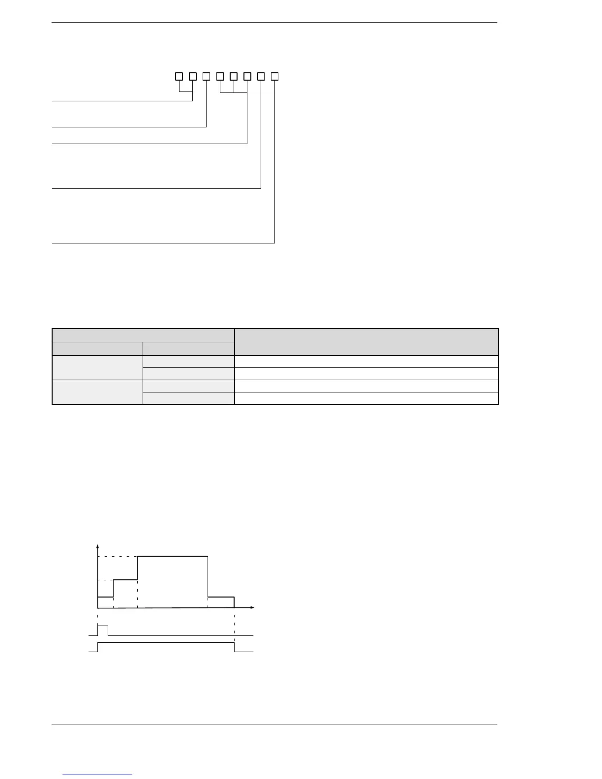
Description of operation
(1) When the trigger R10 in F174 (SP0H) instruction is on, the pulses are output at 1000 Hz from the specified
channel.
(2) When 1000 pulses are counted at 1000Hz, the frequency changes to 2500Hz.
(3) When 3000 pulses are counted at 2500Hz, the frequency changes to 5000Hz.
(4) When 8000 pulses are counted at 5000Hz, the frequency changes to 1000Hz.
(5) When 1000 pulses are counted, the pulse output stops.
0 1000 3000 8000 10000
1000
2500
5000
(Moving distance)
Frequench (speed)
R9120
High−speed
couonter
Elapsed value
Flag
R10
Pulse output
instruction
flag
Note) When the trigger R10 in F174(SP0H) instruction turns on, the pulse output instruction flag will be on.
Once the pulse output stops when the elpased value reached 10000, the high−speed counter control
flag will be off.
FP0R
Phone: 800.894.0412 - Fax: 888.723.4773 - Web: www.clrwtr.com - Email: info@clrwtr.com












 To Next Page