High−level Instructions
3 − 543
The control code, initial speed, maximum speed, acceleration/deceleration time, and target value are
specified by creating the data table “S” to “S+11” on the following page using the user program.
If the frequency is set to 40 kHz or more, specify a duty of 1/4 (25%).
If the frequency for ch2 or ch3 of FP−X Tr type is set to 10kHz or more, specify a duty of 1/4 (25%).
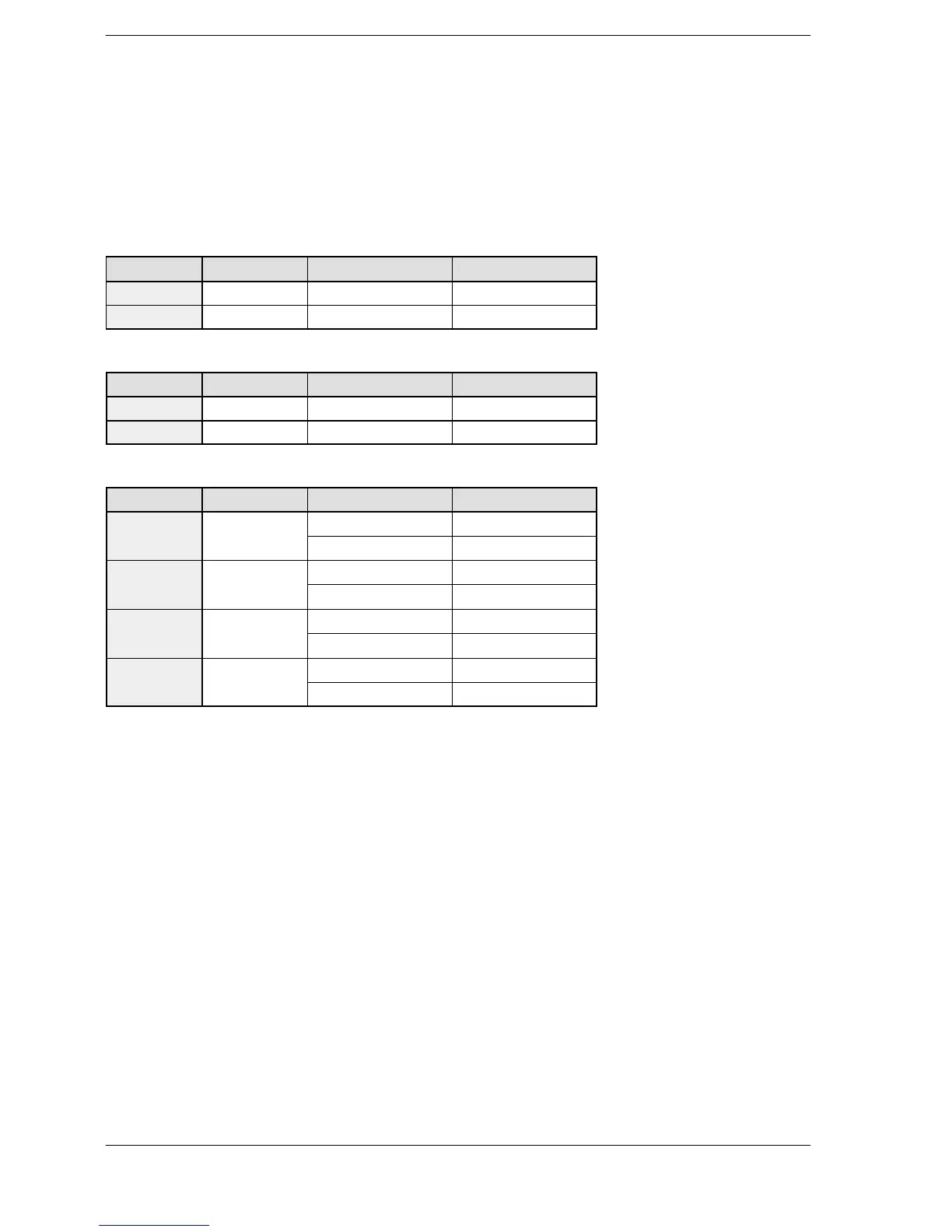
Table of areas used
For FP Σ
Channel no. Control flag Elapsed value area Target value area
ch0 R903A DT90044, DT90045 DT90046, DT90047
ch2 R903C DT90200, DT90201 DT90202, DT90203
For FP−X Ry type
Channel no. Control flag Elapsed value area Target value area
ch0 R911C DT90348, DT90349 DT90350, DT90351
ch1 R911D DT90352, DT90353 DT90354, DT90355
For FP−X Tr type
Channel no. Control flag Elapsed value area Target value area
DT90361 DT90363
Note) There is no ch3 for C14T and C14TD.
Note) The pulse I/O cassette (AFPX−PLS) cannot be installed on the FP −X Tr type.
Note) Use the ch2 and ch3 at up to 20 kHz.
FPΣ/FP−X





 To Next Page