EasyManua.ls Logo

Panasonic FP-E - Page 813

Panasonic FP-E
1334 pages
Print Icon
To Next Page IconTo Next Page
To Previous Page IconTo Previous Page
Loading...
High−level Instructions
3 − 549
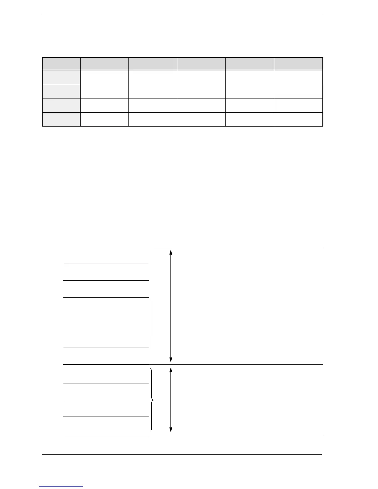
Table of areas used
FP0R
Pulse output
channel No.
Pulse output
instruction flag
Elapsed value area Target value area
Target value area
for match ON/OFF
Correction speed
of initial speed
ch0
R9120
DT90400 to DT90402 to DT90404 to
DT90406
ch0 R9120
DT90400
to
DT90401
DT90402
to
DT90403
DT90404
to
DT90405
DT90406
ch1
R9121
DT90410 to DT90412 to DT90414 to
DT90416
ch1 R9121
DT90410
to
DT90411
DT90412
to
DT90413
DT90414
to
DT90415
DT90416
ch2
R9122
DT90420 to DT90422 to DT90424 to
DT90426
ch2 R9122
DT90420
to
DT90421
DT90422
to
DT90423
DT90424
to
DT90425
DT90426
ch3
R9123
DT90430 to DT90432 to DT90434 to
DT90436
ch3 R9123
DT90430
to
DT90431
DT90432
to
DT90433
DT90434
to
DT90435
DT90436
Precautions during programming
Designate settings for the target value and movement distance so they are within the following range.
K−8,388,608 to +8,388,607
When using in combination with other positioning instructions like F171, designate so the target value is
within the above range, even in those instructions.
When using in application requiring precision, check with the actual machine.
If both the regular program and the inerrupt program contain code for the same channel, make sure both are
not executed simultaneously.
Setting of data table
The linear interpolation can be performed with either combination of (CH0 and CH1) or (CH2 and CH3).
The acceleration time and deceleration time can be specified individually.
S
S+1
Control code
(*1)
S+2
S+3
Composite speed: Initial speed
(Hz)
(*2)
S+4
S+5
Composite speed: Target speed
(Hz)
(*2)
Setting area
Di td
ith
S+6
S+7
Acceleration time (ms)
(*3)
Designated with user program
S+8
S+9
Deceleration time (ms)
(*3)
S+10
S+11
X−axis target value
(*4)
S+12
S+13
Y−axis target value
(*4)
S+14
S+15
X−axis component speed: Initial
speed (Hz)
S+16
S+17
X−axis component speed: Target
speed (Hz)
(
*5
)
Operation result storage area
Parameters
for
each
axis
component
S+18
S19
Y−axis component speed: Initial
(*5)
Parameters
f
or each axis component,
calculated
due
to
instruction
execution
are
stored
here
S+19
Y axis
component
speed:
Initial
speed (Hz)
ca
l
cu
l
ate
d
d
ue to
i
nstruct
i
on execut
i
on, are store
d
h
ere.
S+20
S+21
Y−axis component speed: Target
speed (Hz)

FP0R
Phone: 800.894.0412 - Fax: 888.723.4773 - Web: www.clrwtr.com - Email: info@clrwtr.com