High−level Instructions
3 − 548
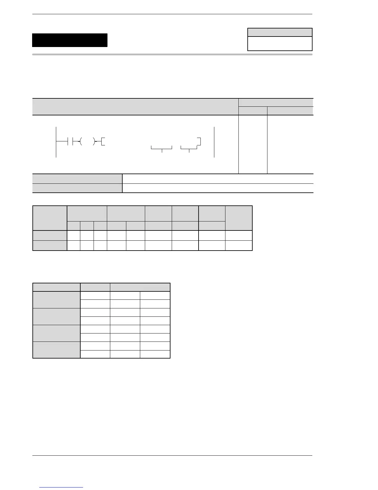
Outline Pulses area output from channel for 2 pulse output, in accordance with
the parameters in the designated data table, so that the path to the
target position forms a straight line.
Program example
Ladder Diagram
Boolean
Ladder Diagram
Address Instruction
10
F175 SPSH , DT100 , K 0
S
n
R10
DF
10
11
12
ST R 10
DF
F175 (SPSH)
DT 100
K0
S Starting 16−bit area for registering data tables
n Channels intended for pulse output (n=0 to 3)
Operands
Operand
Relay Timer/Counter Register
Index
register
Constant
Index
modifier
Operand
WX WY WR SV EV DT I H
modifier
S N/A N/A N/A N/A N/A A N/A N/A A
n N/A N/A N/A N/A N/A N/A N/A A N/A
Description
When the corresponding pulse output instruction flag is off and the trigger is on, pulses are output from
channel ch0 (X−axis) and ch2 (Y−axis), or ch3 (X −axis) and ch4 (Y −axis).
Channel no. Output Output method
ch0 (for X−axis) Y0 CW PLS( )
Y1 CCW SIGN
ch2 (for Y−axis) Y3 CW PLS( )
Y4 CCW SIGN
ch3 (for X−axis) Y5 CW PLS( )
Y6 CCW SIGN
ch4 (for Y−axis) Y7 CW PLS( )
Y8 CCW SIGN
The control code, initial speed, maximum speed, acceleration/deceleration time, and target value are
specified by creating the data table ”S” to ”S+11” on the following page using the user program.
When the elapsed value reaches the final target value, the pulse output stops.
FP0R
Pulse output
(Linear interpolation)
5
F175
(SPSH)
Availability
FP0R
A: Available
N/A: Not Available












 To Next Page