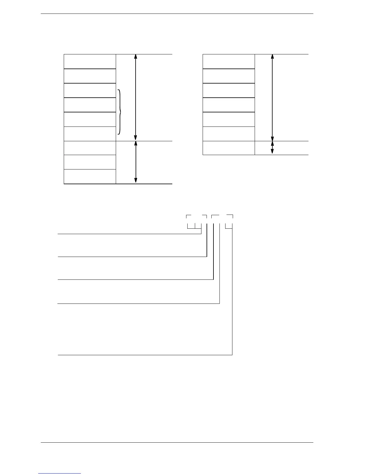
S+8
S+9
X−axis (CH0)
Center position
S+10
S+11
Y−axis (CH2)
Pass position
S+10
S+11
Y−axis (CH2)
Center position
S+12
S+13
Radius
S+12
S+13
Radius
S+14
S+15
X−axis (CH0)
Center position
S+16
S+17
Y−axis (CH0)
Center position
(*1): Specification of control code (specify with H constant)
Operation mode and output method
00: Incremental CW/CCW
02: Incremental PLS + SIGN (forward off / reverse on)
03: Incremental PLS + SIGN (forward on / reverse off)
10: Absolute CW/CCW
12: Absolute PLS + SIGN (forward off / reverse on)
13: Absolute PLS + SIGN (forward on / reverse off)
H □□□□□□□
0: Fixed
Operation connection mode(*4)
0: Stop
1: Continue
Rotation direction (*5)
0:
from CH2−CW axis to CH0−CW axis
1: from CH0−CW axis to CH2−CW axis
Circular method (*6)
0: Pass position setting method
1: Center position setting method
S+1 S
(*2): Composite speed (Frequency) “K constant”
100 Hz to 20 kHz [K100 to K20000]
As a guide, keep the composite speed within the range of the formula below.
Fv[Hz] <= radius[pulse] x 10/scantime[ms]
FPΣ C32T2/FP−X
Setting
area
Designated
with user pro-
gram
Operation result
storage area
Parameters for each
axis component, cal-
culated due to in-
struction execution,
are stored here.
Operation result
storage area
Setting
area












 To Next Page