High−level Instructions
3 − 556
(*3): Target position and pass position
K−8388608 to K8388607
(*4): Operation connection mode
Stop:
When stop (0) is specified, it will stop when the target position is reached.
Continue:
When the following circular interpolation data table is overwritten when continue (1) is specified
after circular interpolation action begins, the following circular interpolation begins when the first
circular interpolation that was started up finishes (target position reached). To finish, specify stop (0)
for this flag (operation connection mode) after the last circular interpolation action has started.
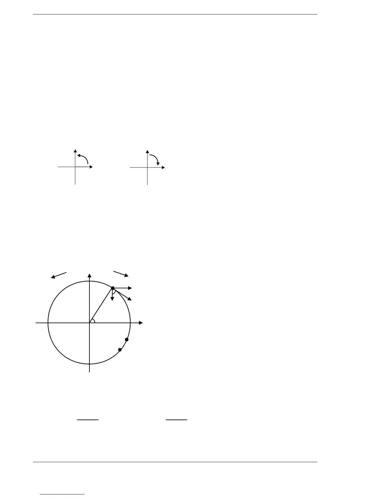
(*5): Rotation direction
Pulses are output according to the designated direction. Operation differs, as indicated below,
depending on the pass position and rotation direction setting.
Direction 1
CH2
CW
CH0
CW
Direction 0
CH2
CW
CH0
CW
(*6): Circular method
Pass position setting method:
The center position and the radius of the circular are calculated by specifying the pass and target
positions for the current position.
Center position setting method:
The radius of the circular is calculated by specifying the center and target positions for the current
position.
Let CH0 be the X−axis, and CH2 be the Y−axis.
Direction 1 Direction 0
Pass position P (Xp, Yp)
Target position E(Xe,Ye)
X (CH0)
|Ye−Yo|
r
|Xe−Xo|
r
O (Xo, Yo): Center point (Center position)
S (Xs, Ys): Start point (Current position)
P (Xp, Yp): Pass point (Pass position)
E (Xe, Ye): End point (Target position)
Fx= Fv sin θ = Fv Fy= Fv cos θ =Fv
Fv: Composite speed
Fx: X−axis component speed
Fy: Y−axis component speed
r: Radius
Current position S (Xs, Ys)
Fy
Fv
Center position O
(Xo, Yo)
θ
θ
Fx
r
Y (CH2)
FPΣ C32T2/FP−X












 To Next Page