WX WY WR SV EV DT I K H
modifier
S N/A N/A N/A N/A N/A A N/A N/A N/A A
n N/A N/A N/A N/A N/A N/A N/A A A N/A
Description
When the corresponding pulse output instruction flag is off and the flag is on, pulses are output from the
specified channels to perform the home return operation.
* For using the pulse output function, it is required to set how to use input/output by system registers.
* C10 and C14 is relay output type, therefore, pulse output cannot be performed.
Description of operation mode
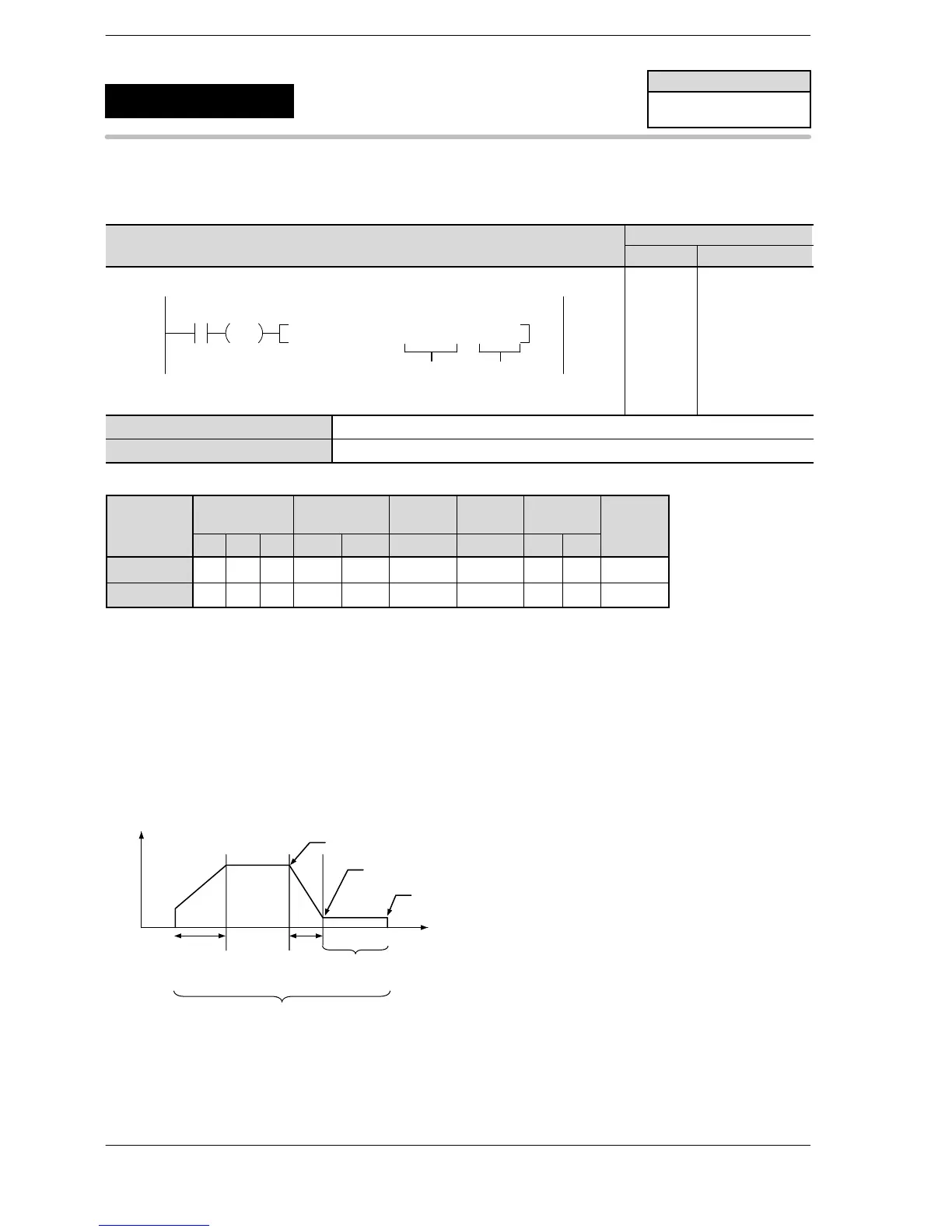
Home return (Type 0) : The home input is available in all sections.
Home return (Type 1) : The home input is available only in the section of creep speed.
Near home input F0(MV) H110, DT90052 (In case of ch0)
Home input X4
(In case of ch0)
Type 1: Home input is available only in the section of creep speed.
Type 0: Home input is available in all sections.
Creep speed
Time
Frequency
FP0R
Pulse output
(Home return)
5
F177
(HOME)
Availability
FP0R
A: Available
N/A: Not Available












 To Next Page