Boolean
Ladder Diagram
Address Instruction
10
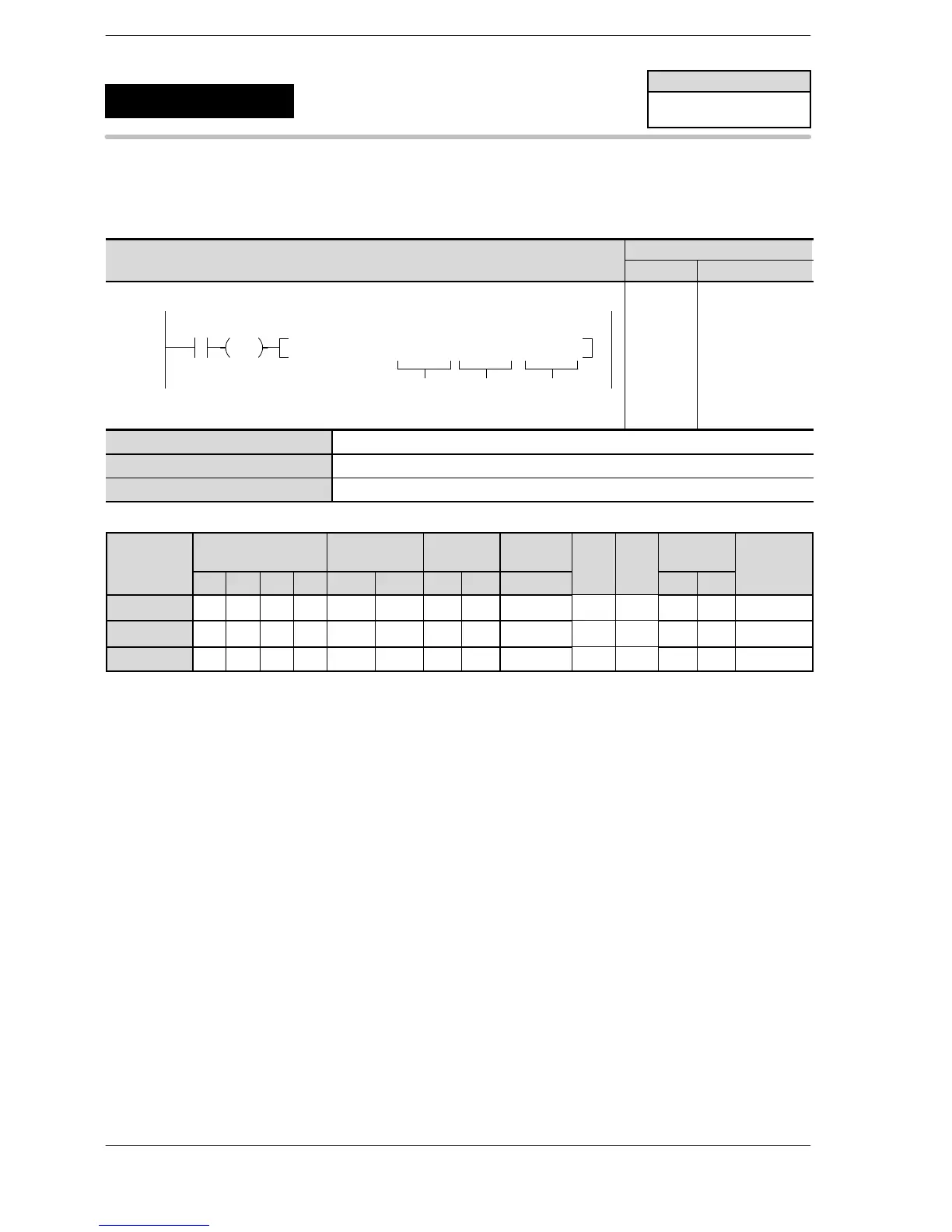
F178 PLSM , DT100 , DT101 , DT200
S1
R3
DF
D
S2
10
11
ST R 3
F178 (PLSM)
DT 100
DT 101
DT 200
S1 Specification of channel No. and No. of moving average.
S2 Counting period
D Starting address of the destination area
Operands
O
K H
modifier
S1 A A A A A A A A A N/A N/A A A A
S2 A A A A A A A A A N/A N/A A A A
D N/A A A A A A A A A N/A N/A N/A N/A A
(*1) I0 to ID
Description
The number of pulses or the pulse period of the specified high−speed counter channel is measured based on
the control data specified by [S1].
In the measurement of the number of pulses, the number of pulses of the specified high−speed counter
counted during the period specified by S2 is counted.
The average of the number of moving average is calculated with the specified period and stored in D and
D+1.
When the number of average is n, −1 is output during the (n*counting period) time after the execution of the
instruction.
In the pulse period measurement in 1us unit, a period of 1 pulse right after the execution of this instruction is
counted and stored in D+2 and D+3.
In the pulse period measurement in 1ms unit, the measured value is stored in D+4 and D+5 every time the
measurement of a period of 1 pulse completes.
The same channel cannot be specified at the same time with other high−speed counter control instructions
<F165(CAM0), F166(HC1S), F167(HC1R)>.
An exclusive control is implemented by the high−speed counter control flags (R9110 to R9115).
The number of channels that the instruction can be executed simultaneously is two.
The trigger should be always ON while the pulse is being measured with this instruction.
Turning OFF the trigger stops the measurement.
FP0R
Input pulse measurement
5
F178
(PLSM)
Availability
FP0R
A: Available
N/A: Not Available












 To Next Page