High−level Instructions
3 − 578
Explanation of example
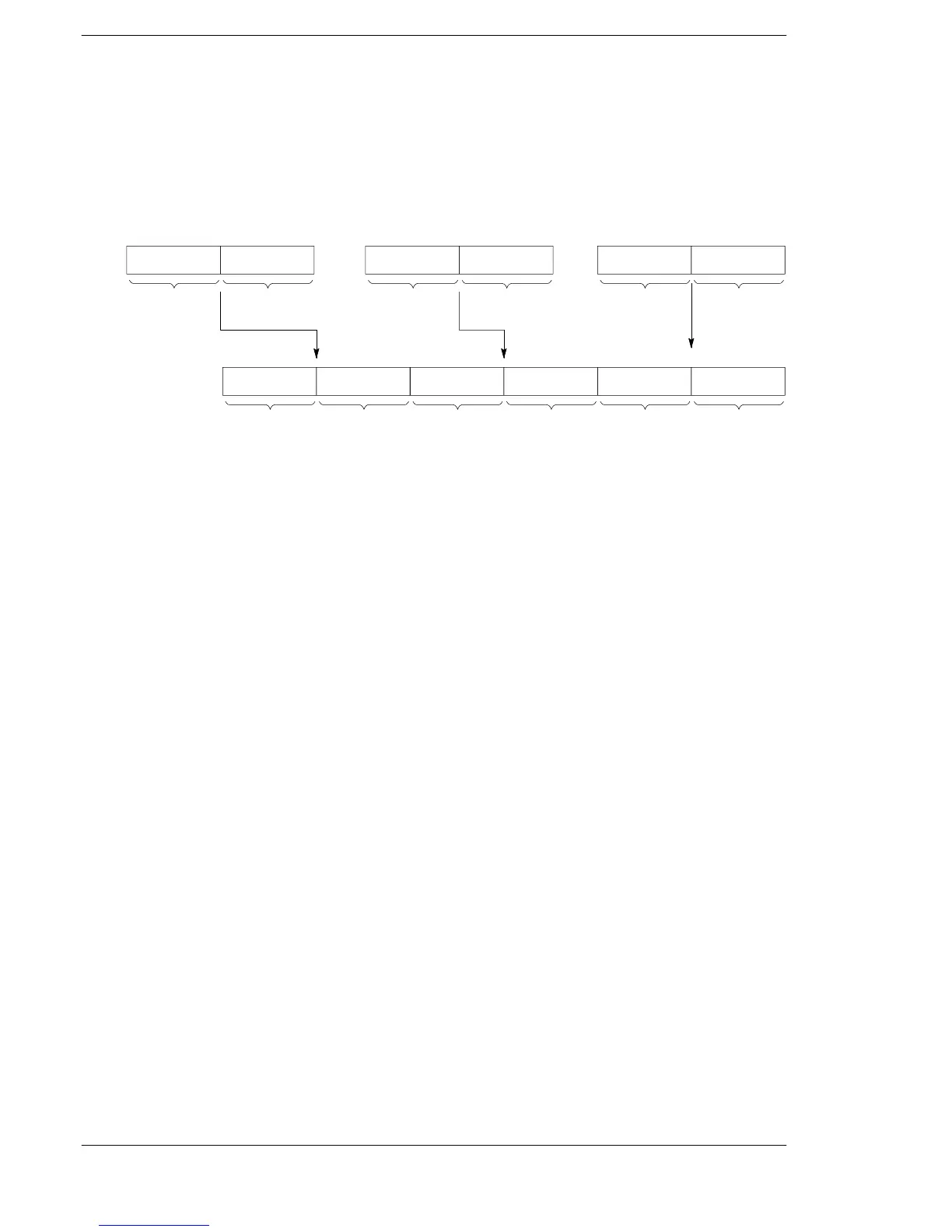
When trigger R0 turns on,
− the contents of deta register DT11 and DT10 are copied to data registers DT41 and DT40.
− the contents of data register DT21 and DT20 are copied to DT43 and DT42.
− the contents of data register DT31 and DT30 are copied to DT45 and DT44.
Contents
of DT11
DT40DT41
Higher
16-bit area
Lower
16-bit area
Contents
of DT10
[S1]
Contents
of DT21
DT42DT43
Higher
16-bit area
Lower
16-bit area
Contents
of DT20
Contents
of DT31
DT44DT45
Higher
16-bit area
Lower
16-bit area
Contents
of DT30
[S3]
[D]
[S2]
Description
The 32-bit data or 32-bit equivalent constant specified by S1, S2 and S3 is copied to the area (6 words)
specified by D when the trigger turns on.
Related instruction
To transfer two types of 32-bit data at once, use the F8 (DMV2) instruction.
Flag conditions
・Error flag (R9007): Turns on and stays on when the area specified using the index modifier
exceeds the limit.
・Error flag (R9008): Turns on for an instant when the area specified using the index modifier
exceeds the limit.












 To Next Page