Boolean
Ladder Diagram
Address Instruction
10
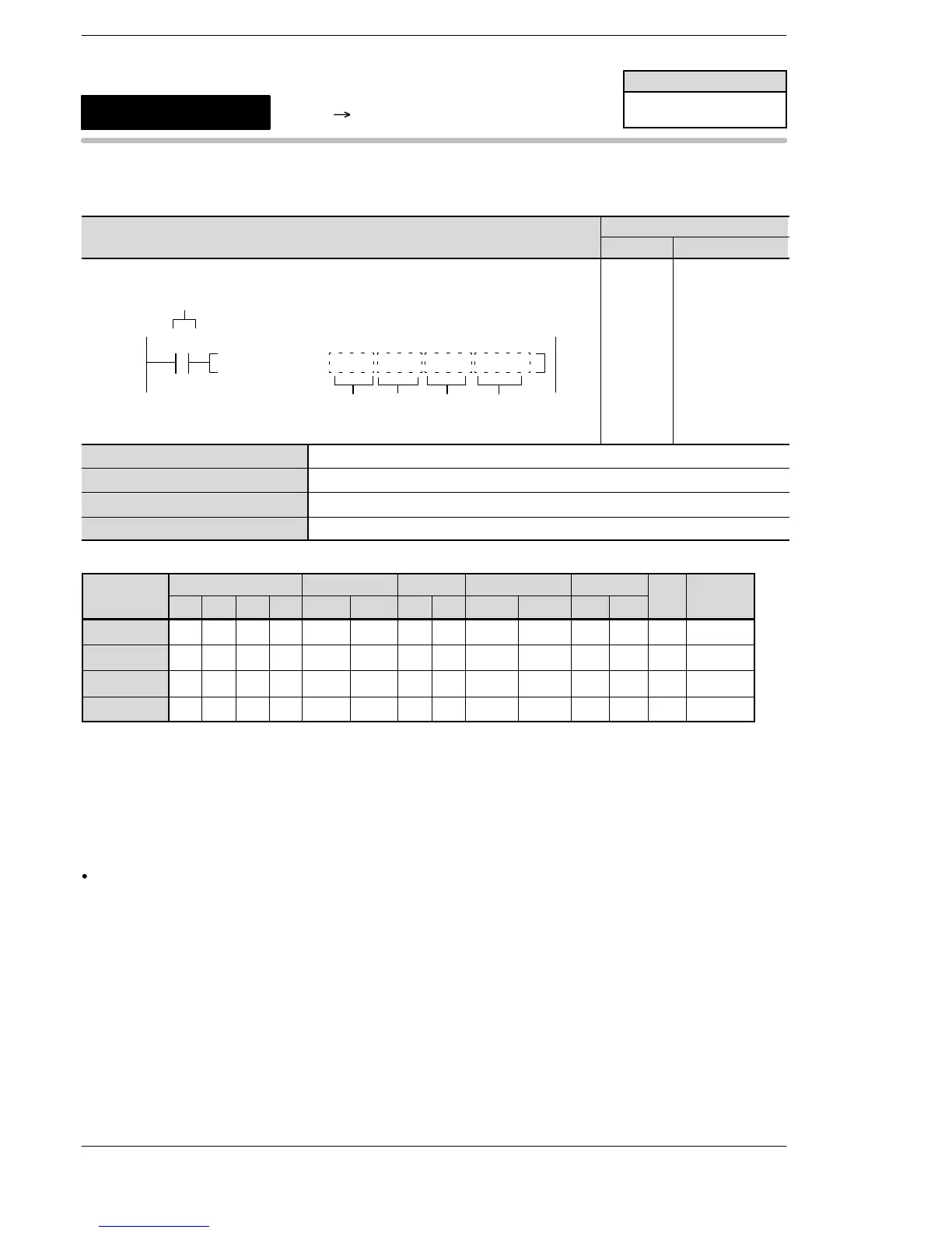
F251 ATOB, D−16, DT10, DT20, DT100
S1
Trigger
R0
S2
DN
M
10
11
ST R 0
F251(ATOB)
MD−16
DT 10
DT 20
DT 100
S1 Control string
S2 Starting 16−bit area for storing ASCII codes
N Conversion method
D Starting 16−bit area for storing binary data of converted result
Operands
modifier
S1 A A A A A A A A A A N/A N/A A A
S2 A A A A A A A A A A N/A N/A N/A A
N A A A A A A A A A A A A N/A A
D N/A A A A A A A A A A N/A N/A N/A A
Operation
Converts the ASCII codes stored in the area specified by S2 to binary data using the conversion method of N
according to 4 control characters specified by S1. The converted result is stored in the area specified by D.
Specifying the various items
Specifying control strings and the meanings [S1]
Ranges of treated data
MD−16 Converts decimal ASCII codes to 16−bit data. −32,768 to +32767
MD−32 Converts decimal ASCII codes to 32−bit data. −2,147,483,648 to +2,147,483,647
M H+16 Converts hexadecimal ASCII codes to 16−bit data.
(Normal direction) 0 to FFFF
M H+32 Converts hexadecimal ASCII codes to 32−bit data.
(Normal direction) 0 to FFFFFFFF
MH−16 Converts hexadecimal ASCII codes to 16−bit data.
(Reverse direction) 0 to FFFF
MH−32 Converts hexadecimal ASCII codes to 32−bit data.
(Reverse direction) 0 to FFFFFFFF
*The details of the normal and reverse directions are described later.
FPΣ/FP−X/FP0R
ASCII Binary conversion
5
F251
(ATOB)
Availability
FP−X/FPΣ 32k/FP0R
A: Available
N/A: Not Available












 To Next Page