High−level Instructions
3 − 655
Outline Executes the linear output according to the elapsed time from the start
by performing scaling with the output initial value, target value and time
range.
Program example
Boolean
Ladder Diagram
Address Instruction
10
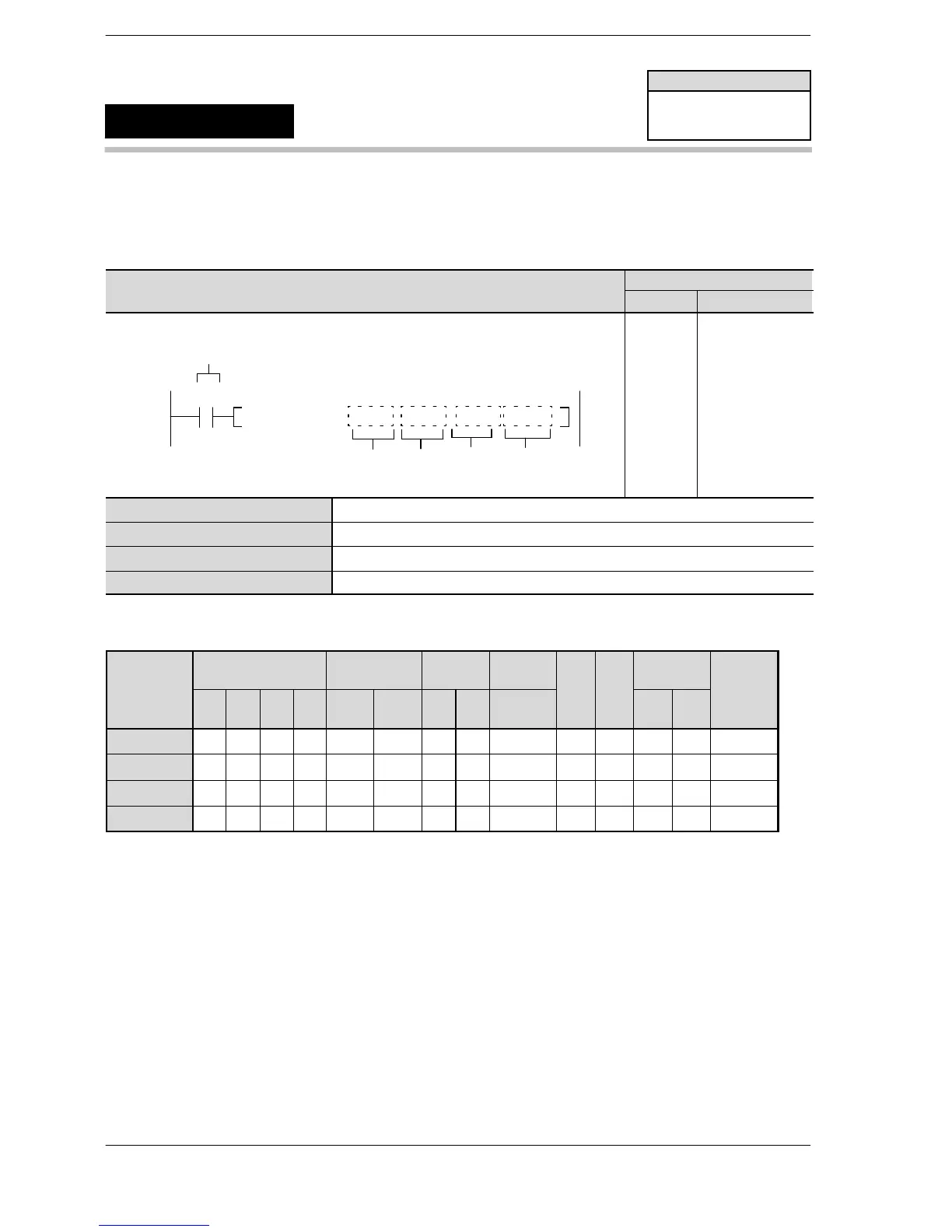
F284 RAMP, DT0, DT 1, DT2, DT10
S1
Trigger
R0
S3
S2
D
10
11
ST R 0
F284 (RAMP)
DT 0
DT 1
DT 2
DT 10
S1 16−bit equivalent constant or 16−bit area for storing initial values
S2 16−bit equivalent constant or 16−bit area for storing target values
S3 16−bit equivalent constant or 16−bit area for storing time range
D Area where output result is stored
Operands
Relay Timer/Counter Register
Index
register
Operand
WX WY WR WL SV EV DT LD
In
(*1)
SWR SDT
K H
modifier
S1 A A A A A A A A A A A A A A
S2 A A A A A A A A A A A A A A
S3 A A A A A A A A A A A A A A
N N/A A A A A A A A A N/A N/A N/A N/A A
(*1) I0 to ID
Operation
Executes the linear output according to the elapsed time from the start by performing scaling with the 16 −bit
output initial value specified by S1, the 16−bit output target value specified by S2 and the 16−bit output time
range (ms unit) specified by S3.
Precautions during programming
Max. 1 scan time error in the output time range occurs occasionally.
FP–e
FP−X V2.0 or more
FPΣ V3.10 or more
FP0R
Inclination output of 16−bit data
F284
(RAMP)
Availability
A: Available
N/A: Not Available
Phone: 800.894.0412 - Fax: 888.723.4773 - Web: www.clrwtr.com - Email: info@clrwtr.com












 To Next Page