High−level Instructions
3 − 664
Description
The output value (double word data) stored in the area specified by D is controlled based on whether or not
the input value (double word data) specified by S3 falls within the dead-band bounded by the upper and lower
limits set in S1 and S2.
The output value is determined based on the following conditions:
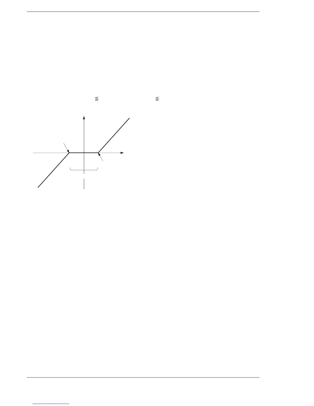
When the lower limit S1+1 and S1 are greater than the input value S3+1 and S3, the input value S3+1 and S3
minus the lower limit value S1+1 and S1 are stored in D+1 and D as the output value.
When the upper limit S2+1 and S2 are less than the input value S3+1 and S3, the input value S3+1 and S3
minus the upper limit value S2+1 and S2 are stored in D+1 and D as the output value.
When Lower limit S1+1 and S1
Input value S3+1 and S3 Upper limit S2+1 and S2, zero is stored in D+1
and D as the output value.
Output value D+1 and D
In this range, zero is output.
Input value S3+1 and S3
Lower limit of deadband
S1+1 and S1
Upper limit of deadband S2+1 and S2
0
Flag conditions
・Error flag (R9007): Turns on and stays on when:
・Error flag (R9008): Turns on for an instant when:
− The area specified using the index modifier exceeds the limit.
− S1 > S2.
・Carry flag (R9009): Turns on for an instant when the calculated result is overflowed or
underflowed.
・= flag (R900B): Turns on when the input value is recognized as “0.”





 To Next Page