2-2
2.1 Parts and Functions
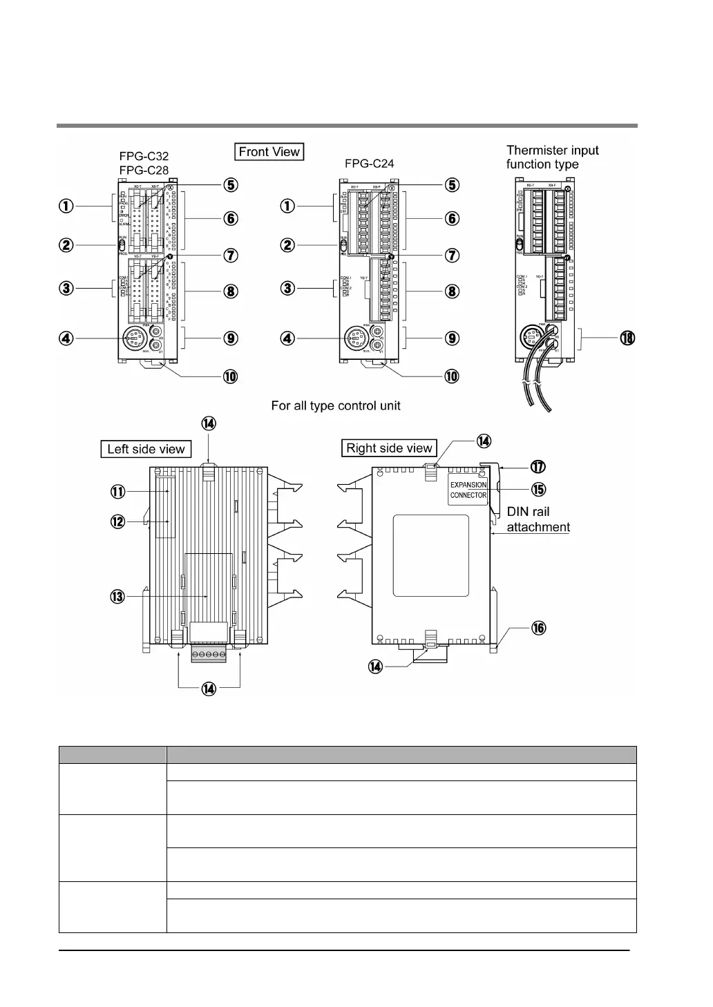
① Status indicator LEDs
These LEDs display the current mode of operation or the occurrence of an error.
LED LED and operation status
Lights when in the RUN mode and indicates that the program is being executed.
RUN (green)
It flashes during forced input/output. (The RUN and PROG. LEDs flash
alternately.)
Lights when in the PROG. Mode and indicates that operation has stopped.
Lights when in the PROG. Mode during forced input/output.
PROG. (green)
It flashes during forced input/output. (The RUN and PROG. LEDs flash
alternately.)
Flashes when an error is detected during the self-diagnostic function. (ERROR)
ERROR/ALARM
(red)
Lights if a hardware error occurs, or if oepration slows because of the program,
and the watchdog timer is activated. (ALARM)