EasyManua.ls Logo

Panasonic FV-0511VHL1 - User Manual

Panasonic FV-0511VHL1
16 pages
Print Icon
To Next Page IconTo Next Page
Loading...
OPERATING AND INSTALLATION
INSTRUCTIONS
READ AND SAVE THESE INSTRUCTIONS
Thank you for purchasing this Panasonic product.
Please read these instructions carefully before attempting to install, operate or service
the Panasonic product. Please carefully read the “IMPORTANT INSTRUCTIONS”.
Failure to comply with instructions could result in personal injury or property damage.
Please explain to users how to operate and maintain the product after installation,
and this booklet should be presented to users.
Please retain this booklet for future reference.
Fan Heater
FV-0511VHL1
FV-0511VH1
FV-0511VHL1
Model No.
FV-0511VH1
Contents
IMPORTANT INSTRUCTIONS
DESCRIPTION
UNPACKING
SUPPLIED ACCESSORIES
FEATURES
DIMENSIONS
INSTALLATION (WIRING DIAGRAM)
INSTALLATION (NEW CONSTRUCTION)
INSTALLATION (RETROFIT)
OPERATION
MAINTENANCE
PRACTICAL GUIDE TO INSTALLATION
SPECIFICATIONS
PRODUCT SERVICE
-----------------2~4
------------------------------------5
--------------------------------------6
-----------------------6
-------------------------------------6~7
-------------------------------------7
------------8
----8~11
--------------------12
-------------------------------------13
-----------------------------14~15
--
BACK COVER
--------------------
BACK COVER
-----------------
BACK COVER

Other manuals for Panasonic FV-0511VHL1

Question and Answer IconNeed help?

Do you have a question about the Panasonic FV-0511VHL1 and is the answer not in the manual?

Summary

Important Safety Instructions

Explanation of Symbol Word Panels

Explains hazard level symbols (Warning, Caution, Notice) and instruction symbols.

General Warnings

Provides crucial safety warnings regarding usage, installation, and maintenance.

Cautionary Notes

Notice

Provides information on parallel connections and ventilation air requirements.

Description

Unpacking and Supplied Accessories

Features

Heater Performance

Details the PTC heater for quick and efficient bathroom warming.

Optimum Ventilation Performance

Explains Smart Flow microchip technology for duct resistance adaptation.

Outstanding Energy Savings

Highlights DC motor technology and Pick-A-Flow™ CFM options.

Dimensions

Installation (Wiring Diagram)

Installation (New Construction)

Step 1: Preparation

Disconnects plug, removes adapter, and removes tape from damper/adapter.

Step 2: Install Flex-Z Fast Bracket

Bends tabs and installs bracket to joists using tapping screws.

Step 4: Junction Box and Conduit

Secures conduit or stress relief to junction box knock-out hole.

Step 5: Duct Installation

Installs and seals a 4 or 6 inch circular duct to the adaptor.

Step 6: Install Adaptor

Installs the adaptor to the Flex-Z Fast™ bracket using self-drilling screws.

Step 7: Wiring and Grounding

Connects house wires to fan heater wires following codes and grounding.

Step 8: Secure Fan Body

Secures fan body to bracket, connects plug, and fastens body to adaptor.

Step 9: Ceiling Finish

Aligns ceiling hole, seals gap between flange and ceiling.

Step 10: Grille Blade Adjustment

Adjusts grille blade orientation for desired warm air flow direction.

Step 12: Connector and Grille Mounting

Ensures connector is seated and mounts grille carefully, avoiding wire pinching.

Step 13: Adjust Pick-A-Flow Switch

Adjusts the Pick-A-Flow™ switch for ventilation air volume.

Step 14: Mount Grille

Inserts mounting spring and mounts the grille to the fan body.

Installation (Retrofit)

Step 1: Prepare Opening

Removes existing equipment and cuts ceiling opening to specified size.

Step 2: Secure Flex-Z Fast Bracket

Secures bracket to joists with tapping screws, leaving existing duct/wiring.

Step 3: Connect Duct and Adaptor

Follows new construction steps for connecting circular duct to adaptor.

Step 4: Install Adaptor

Installs the adaptor to the Flex-Z Fast™ bracket using self-drilling screws.

Step 5: Secure Fan Body

Secures fan body to bracket with screws, connects plug, and fastens to adaptor.

Step 6: Final Grille Mount

Follows new construction steps for grille mounting (Steps 10-14).

Operation

Operating Instructions

Details switch modes (Heat, Vent, Light, Night-Light) and their functions.

Timer Function

Explains the 2-hour auto-off timer for Heat/Vent switches.

Maintenance

Filter Maintenance Instructions

Provides steps for cleaning the filter every three months.

Grille and Fan Body Maintenance

Outlines annual cleaning procedures for the grille and fan body.

Practical Guide to Installation

Specifications

Product Service

Overview

This document outlines the operating and installation instructions for the Panasonic Fan Heater, models FV-0511VH1 and FV-0511VHL1. It emphasizes safety precautions, installation procedures for both new construction and retrofits, operational guidelines, and maintenance instructions.

Function Description

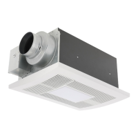
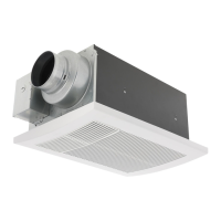
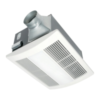
The Panasonic fan heater utilizes a sirocco fan driven by a DC motor, powered by an integral transformer. This design ensures a long operating life, high dynamic response, higher speed ranges, and energy efficiency. The fan heater is equipped with a 1600W PTC (Positive Temperature Coefficient) heater, which provides quick and efficient warming, particularly suitable for bathrooms. A thermostat and thermal cut-off switch are integrated for safety, preventing abnormal temperature rise.

For ventilation, the unit incorporates Smart Flow microchip technology. This technology monitors static pressure within the duct system and adjusts the fan's RPM accordingly, ensuring the fan performs as rated despite varying duct lengths, elbows, and other resistance factors. This feature helps avoid potential installation issues and ensures optimal ventilation performance.

The FV-0511VHL1 model also includes a lighting unit with a 10W LED light, offering illumination comparable to a standard 40W incandescent light. It also features a night light function, consuming approximately 0.1 to 0.4W. This model is Type IC-inherently Protected.

Usage Features

Operating Modes: The fan heater offers several operating modes:

  • "Heat" Mode: Heats the bathroom.
  • "Vent" Mode: Ventilates the bathroom.
  • "Heat" and "Vent" Mode: Exhausts moisture while simultaneously warming the bathroom.
  • "Light" Mode (FV-0511VHL1 only): Turns on the main LED light.
  • "Night-Light" Mode (FV-0511VHL1 only): Turns on the night light.

Pick-A-Flow™ Feature (Ventilating Mode Only): The fan heaters come with Pick-A-Flow™ speed options, allowing users to select between 50, 80, or 110 CFM (Cubic Feet per Minute) for constant air volume. The factory setting is 80 CFM. This switch is located on the face of the WhisperWarm® fan. Note that the Pick-A-Flow™ switch is not available to set ventilation air volume while operating in the heating and ventilating mode, as adequate ventilation is automatically provided to reduce heat loss in a bathroom.

Timer Function: A timer function is available for both "heating" and "heating and ventilating" modes. This feature automatically turns off the heat switch circuit after 2 hours if the user forgets to turn off the switch, thereby reducing power consumption. To reset the timer and resume operation, the "Heat" or "Vent" switch must be moved back to the "OFF" position.

Airflow Direction Adjustment: The orientation of the grille blades can be adjusted to direct the warm air flow as desired. Arrow marks on the grille blades indicate the direction of the warm air flow.

Quiet Operation: The blower utilizes a high-capacity sirocco fan developed to reduce noise levels.

Energy Efficiency: Built with DC motor technology, the fan's DC motor for ventilating is 30% - 70% more energy efficient than traditional AC motors.

Maintenance Features

Regular maintenance is crucial for the safe and efficient operation of the fan heater.

Filter Maintenance:

  • Frequency: The filter must be maintained every three months.
  • Removal: To remove the filter, squeeze the mounting spring and carefully pull down the specified side of the grille.
  • Cleaning: After removing the filter from the fan body, use a vacuum cleaner to remove dust and dirt.
  • Reinstallation: Insert the filter until it clicks, then reinstall the grille.

Grille and Fan Body Maintenance:

  • Frequency: The grille and fan body must be maintained every year.
  • Grille Cleaning: Clean the grille without submerging it in water. Use a non-abrasive kitchen neutral detergent, then wipe dry with a clean cloth. Ensure the grille is completely dry before reinstallation.
  • Fan Body Cleaning: Remove dust and dirt from the fan body using a vacuum cleaner. Afterward, use a cloth dampened with a non-abrasive kitchen neutral detergent to remove any remaining dirt, then wipe dry with a clean cloth.
  • Grille Removal for Cleaning: Similar to filter removal, squeeze the mounting spring and pull down the specified side of the grille to access the fan body.
  • Reinstallation: After cleaning, reinstall the grille.

Safety Precautions During Maintenance:

  • Always disconnect the power source at the circuit breaker panel and ensure it is locked to prevent accidental power-on before servicing or cleaning.
  • Ensure heating elements and the lighting unit are cool before handling.
  • Wear gloves during installation and maintenance procedures.
  • Never use gasoline, benzene, paint thinner, or other harsh chemicals for cleaning.
  • Do not immerse the motor or heater in water. Avoid soaking resin parts in water hotter than 140 °F (60 °C).
  • Do not insert fingers or foreign objects into the heating elements.
  • Unauthorized modification, repair, or disassembly is strictly prohibited. Any maintenance beyond user-level tasks should be performed by a specialized serviceman.
  • Mount the grille carefully to avoid pinching lead wires.

Panasonic FV-0511VHL1 Specifications

General IconGeneral
Voltage120 V
ENERGY STAR CertifiedNo
Duct Diameter4 inches
Air Flow50 CFM
Safety FeaturesThermal Fuse Protection

Related product manuals