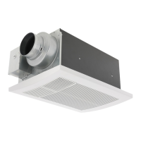
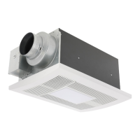
Fan body
Disconnect plug connector from receptacle
and remove adaptor from fan body by
removing the machine screw (M4X8) before
installation. (Fig.1)
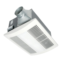
The fan heater can be adjusted to be installed between joists of any pitch between 16" and 24" on center.
To reduce the risk of fire, do not store
or use gasoline or other flammable
vapors and liquids in the vicinity of the
fan heater.
Disconnect power source before
working on the fan heater.
Installation work and electrical wiring must be
done by qualified person(s) in accordance with
all applicable codes and standards, including
fire-rated construction. Neither unauthorized
modification, repair nor disassembly is allowed.
Please wear gloves during the following
installation procedure.
WARNING
CAUTION
Fig.1
IMPORTANT:
Remove the tape from damper and adaptor
before installation. As shown below:
Tape
Adaptor
Damper
Adaptor
English
8
STEP 1
Plug
connector
Machine screw
(M4X8)
INSTALLATION
(
WIRING DIAGRAM
)
INSTALLATION
(
NEW CONSTRUCTION
)
FV-0511VHL1FV-0511VH1
PCB
VENTILATION
WHITE
GREEN
RED
BLACK
STEPPER
MOTOR
HEAT
THERMAL
CUT-OFF
MOTOR
STEPPER
MOTOR
MOTOR
AC120 V
60 Hz
3
2
1
4
3
2
1
4
3
2
1
4
5
3
2
1
4
5
3
2
1
4
5
3
2
1
4
5
6
L
N
1
2
3
WHITE
RED
THERMOSTAT
HEATER
YELLOW
BLACK
BLACK
BLUE
TAB2
TAB3
TAB4
TAB5
TAB1
LED
PCB
BLUE
NIGHT LIGHT
VENTILATION
WHITE
WHITE
GREEN
RED
BLACK
BLACK
HEAT
3
2
1
3
2
1
L
N
AC120 V
60 Hz
AC120 V
60 Hz
3
2
1
4
3
2
1
4
3
2
1
4
5
3
2
1
4
5
3
2
1
4
5
3
2
1
4
5
6
L
N
LIGHT
1
2
3
WHITE
RED
THERMOSTAT
HEATER
YELLOW
BLACK
BLACK
BLUE
TAB2
TAB3
TAB4
TAB5
TAB1
THERMAL
CUT-OFF
(219
º
F(104
º
C))
(219
º
F(104
º
C))
 Loading...