EasyManua.ls Logo

Panasonic FV-SW20VEC1 - User Manual

Panasonic FV-SW20VEC1
10 pages
Print Icon
To Next Page IconTo Next Page
Loading...
nasonic
Installation and Operating Instructions
Wall Control
=

�mos
FBB

Cl Cl
Q


Q
Cl

Supply au




BBB

BB


Time


8 8

 
T
 
OFF/ON

Filter

Boost

Vent
Pss 3s
nanic

 FV-SW20VEC1



















Question and Answer IconNeed help?

Do you have a question about the Panasonic FV-SW20VEC1 and is the answer not in the manual?

Summary

General Safety Information

Supplied Accessories

Dimensions

Installation

Wiring Preparation

Prepare wires for connecting the product and wall control.

Installing the Wall Control

Steps for physically mounting the wall control unit.

Button and Display Description

OFF;ON Button

Controls product standby and running states.

Filter Reset Button

Resets accumulated running time after filter maintenance.

Boost Button

Activates or deactivates the Boost mode.

Vent Button

Sets supply and exhaust air volume.

Boost Display Light

Indicates when Boost mode is active (green light).

In;Out Button

Displays inside or outside temperature and humidity.

Time Button

Sets Boost time and ASHRAE time.

Set Button

Confirms air volume or time settings.

Up;Down Arrow Buttons

Adjusts air volume or time settings.

Filter Maintenance Display

Indicates when the filter needs cleaning or changing.

ASHRAE;Boost Time Display

Shows set ASHRAE and Boost operating times.

Defrost Mode Display

Shows the product in low-temperature protection mode.

Inside;Outside Temp & Humidity Display

Displays internal and external environmental conditions.

Air Volume Display

Shows supply and exhaust air volumes.

COSMOS Display

Indicates when the Cosmos module is connected.

Error Code Display

Shows fault codes when the product is in failure.

Operation

Standby Mode

Unit status when not actively running functions.

Function Mode

General operation modes for air volume settings.

Defrost Mode

Automatic mode for low outdoor temperatures.

Boost Mode

High-performance mode for increased air exchange.

Filter Reset

Procedure to reset filter maintenance indicator.

Troubleshooting

Specifications

Product Service

Overview

This document outlines the installation, operation, and maintenance of the Panasonic FV-SW20VEC1 Wall Control, designed to manage Panasonic ventilation products. It emphasizes safety precautions, proper installation procedures, and detailed descriptions of the control's functions and display.

General Safety Information

The manual begins with crucial safety information, categorized by hazard levels:

  • WARNING: Denotes potential hazards that could result in death or serious injury.
  • CAUTION: Denotes hazards that could result in minor injury.
  • NOTICE: Denotes hazards that could result in property damage.

Specific warnings include:

  • Do not install using unapproved methods. Installation must be performed by qualified personnel in accordance with all applicable codes.
  • Disconnect the power source before working on the product.
  • Do not disassemble the unit, as it may cause fire or electric shock.
  • Avoid installing the unit in high humidity spaces.
  • Do not spray flammable cleaner directly onto the controller.
  • Do not touch the controller with wet hands or pour water on it to prevent fire or electric shock.
  • Do not install where flammable gas may leak.
  • Discontinue use immediately if abnormal operation occurs.
  • Use the unit only for its intended purpose.

Cautions include:

  • Wear personal protective equipment during installation.
  • Use only special-purpose or dedicated parts, such as provided mounting fixtures, to prevent injury.
  • Inspect all wiring connections to ensure correct current capacity.
  • Disconnect power by switching off the wall control, then the main switch, and unplugging the power plug before working on the unit.
  • Do not press the wall control screen, as it may cause a fault code, electric shock, or screen breakage.
  • Select an easily accessible and dry location, not directly exposed to sunshine.
  • Choose a flat location to prevent distortion, which could damage the wall control or cause a fault code.
  • Install the control at a height where the display is easily viewed and accessed (standard height is about 5 ft or 1.5 m from the ground).
  • Ensure sufficient space around the installation position.

Installation

The installation process involves several steps:

  1. Wiring Preparation:

    • Use a cable (14AWG~26AWG) for connecting the product and wall control, not exceeding 33.3 ft (10 m) in length.
    • Strip insulation cover for each wire as shown in the diagram (3 1/2~4 inches or 90~100 mm, with 1/4 inch or 7 mm of copper wire exposed).
    • Attach matching wire labels to each side of the cable.
  2. Installing the Wall Control:

    • Open the knock-out hole and remove maintenance plates 1 and 2 and the wiring cover.
    • Thread cables through conduits and install conduits into knock-out holes.
    • Insert cables into the corresponding terminals of the product, ensuring wire labels match terminal labels and screws securely fasten copper wires without exposure.
    • Re-install wiring covers and maintenance plates.
    • Remove the face plate backing cover from the backing plate using a small flat screwdriver.
    • Temporarily place the face plate backing cover on the wall, mark the terminal hole and screw positions.
    • Remove the face plate backing cover, cut the terminal hole, and drill screw holes (Ø5/32 ft or Ø4 mm).
    • Insert wall anchors and fix the face plate backing cover on the wall with two screws.
    • Route the cables from the unit to the terminal hole.
    • Insert cables into the corresponding terminals of the wall control according to the lead wire labels.
    • Fix the wall control screen to the face plate backing cover, ensuring cables are not caught by the circuit board or resin clip, which could cause electrical leakage. Do not press the screen to avoid distortion or breakage.

Button and Display Description

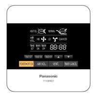
The wall control features several buttons and display elements:

  • OFF/ON Button (1): Toggles product standby/running mode.
  • Filter Reset Button (2): Resets accumulated running time after filter maintenance.
  • Boost Button (3): Activates/deactivates Boost Mode.
  • Vent Button (4): Sets supply air volume/exhaust air volume.
  • Boost Display Light (5): Green light indicates Boost mode is on.
  • In/Out Button (6): Displays inside or outside temperature and humidity.
  • Time Button (7): Sets Boost time and ASHRAE time.
  • Set Button (8): Confirms air volume/time settings.
  • ▲▼ Buttons (9): Sets air volume and time (min, min/h).
  • Filter Maintenance Display (10): Indicates when the filter needs cleaning or changing.
  • ASHRAE/Boost on time Display (11): Displays ASHRAE time and Boost time.
  • Display Defrost Mode (12): Shows when the product is in low-temperature protection mode (Air exchange, Circulation, Stop operating).
  • Display Inside & Outside Temperature and Humidity (13): Shows current inside and outside temperature and humidity.
  • Air Volume Display (14): Shows supply and exhaust air volume.
  • COSMOS Display (15): Appears when the Cosmos module is connected.
  • Error Code Display (16): Displays error codes for troubleshooting.

Operation

Standby Mode:

  • Pressing the "OFF/ON" button starts/stops the unit.
  • The inside temperature (°F) and humidity (%) are displayed.
  • The unit operates in the last mode before stopping.
  • When connected to the wall control, the FV-20VEC1's control panel is disabled. If the wall control is disconnected, the ERV controls are enabled.

Function Mode:

  • Air Volume Setting (Default: 120 CFM):

    1. Press "Vent" to switch between supply and exhaust air volume.
    2. Press "▲▼" to choose and adjust the volume (60, 80, 100, 120, 140, 160, 180, 200).
    3. Press "Set" again to confirm the setting.
  • ASHRAE Time Setting (Default: 60 min/h):

    1. Press "Time" to change the ASHRAE time.
    2. Press "Set" and then "▲▼" to adjust the ASHRAE time (60, 50, 40, 30, 20, 10).
    3. Press "Set" again to confirm the setting.
    • For more details on ASHRAE intermittent timer control, refer to the FV-20VEC1 manual.
  • In/Out Temperature and Humidity Display:

    • Press "In/Out" to switch between displaying inside and outside temperature and humidity.
  • Defrost Mode:

    • When the outdoor temperature is below 14 °F, the ERV enters defrost mode, and a defrost icon is displayed.
    • Heat exchange: Defrost icon is displayed.
    • Circulation: Icon blinks quickly.
    • Stop operating: Defrost icon is displayed.
    • Notes on Defrost Mode:
      • The maximum ventilation air volume setting is 180 CFM.
      • If ventilation air volume is 60 CFM~120 CFM, circulation air volume is 180 CFM.
      • If ventilation air volume is 130 CFM~180 CFM, circulation air volume is 230 CFM.
      • For more detailed information, refer to the FV-20VEC1 manual.
  • Boost Mode:

    • Press "Boost" to enter boost mode; supply and exhaust air volume remain constant at 200 CFM.
    • Boost on-time setting (Default: 20 min):
      1. Press "Time" to change the boost on-time, and press "▲▼" to adjust (60, 50, 40, 30, 20, 10).
      2. Press "Set" to confirm the setting.
    • Exit Boost Mode:
      1. The timer finishes.
      2. Press "Boost" again.
      3. Press "Vent" to set supply and exhaust air volume, then the ERV will exit boost mode.
    • Note: Boost air volume will be constant at 180 CFM when the outdoor temperature is below 14 °F. For more details on Boost features and functions, refer to the FV-20VEC1 manual.
  • Filter Reset:

    • When the filter requires cleaning, "✓ Filter" will display.
    • Press "Filter" for 3 seconds to cancel the "✓ Filter" display after filter maintenance.
    • For more information on filter maintenance, refer to the FV-20VEC1 maintenance label on the front panel.

Troubleshooting

If the product malfunctions, a fault code will be displayed. The manual provides a list of common fault codes and recommended actions:

  • F01 (Wall control communication error): Disconnect power and contact the dealer to check wall control wiring.
  • F02 (Cosmos communication error): Disconnect power and contact the dealer for repair.
  • F03 (PCB board error): Disconnect power and contact the dealer for repair.
  • F10 (OA temperature sensor error): Disconnect power and contact the dealer for repair.
  • F11 (OA humidity sensor error): Disconnect power and contact the dealer for repair.
  • F12/F13 (RA temperature and humidity sensor error): Disconnect power and contact the dealer for repair.
  • F20 (SA motor error): Disconnect power and contact the dealer for repair.
  • F21 (EA motor error): Disconnect power and contact the dealer for repair.
  • F30 (OA damper error): Disconnect power and contact the dealer for repair.
  • F31 (EA damper error): Disconnect power and contact the dealer for repair.
  • F32 (Center damper error): Disconnect power and contact the dealer for repair.

Product Service

  • Warning Concerning Removal of Covers: The unit should only be serviced by qualified technicians.
  • The product is designed for minimal maintenance.
  • For service or parts, contact the Panasonic Call Center.

Panasonic FV-SW20VEC1 Specifications

General IconGeneral
ManufacturerPanasonic
CategoryController
ModelFV-SW20VEC1
Power SupplyAC
Frequency60Hz
Maximum Current0.5A
Voltage120V
Operating Temperature14°F ~ 104°F (-10°C ~ 40°C)

Related product manuals