EasyManua.ls Logo

Panasonic JS-960 Series User Manual

Panasonic JS-960 Series
149 pages
To Next Page IconTo Next Page
Page #1 background image
ORDER NO. MSBU1111001C0
G20
Service Manual
JS-960 Series
POS Workstation
List of models
Model No. Display Style Touch Panel CPU
Magnetic
Stripe Reader
Rear
Display
JS-960WSUM51 15 inch LCD Upright Capacitive
Intel® Celero
P4500 1.86 GHz
JS-960WSUM61 15 inch LCD Upright Capacitive
Intel® Core™ i5
520 M 2.4 GHz
JS-960WSUR50 15 inch LCD Upright Resistive
Intel® Celero
P4500 1.86 GHz
JS-960WSUR51 15 inch LCD Upright Resistive
Intel® Celero
P4500 1.86 GHz
12 inch (ISO,
Dark)
JS-960WSUC50 15 inch LCD Upright Capacitive
Intel® Celero
P4500 1.86 GHz
JS-960WSUC51 15 inch LCD Upright Capacitive
Intel® Celero
P4500 1.86 GHz
12 inch (ISO,
Dark)
JS-960WS0M51 15 inch LCD Upright Capacitive
Intel® Celero
P4500 1.86 GHz
12 inch (ISO,
Dark)
Yes
JS-960WSHM51 15 inch LCD Upright Capacitive
Intel® Celero
P4500 1.86 GHz
12 inch (ISO,
Dark)
Yes
JS-960WS0M53 15 inch LCD Upright Capacitive
Intel® Celero
P4500 1.86 GHz
12 inch (ISO,
Dark)
JS-960WS0R50 15 inch LCD Upright Resistive
Intel® Celero
P4500 1.86 GHz
JS-960WS0R51 15 inch LCD Upright Resistive
Intel® Celero
P4500 1.86 GHz
12 inch (ISO,
Dark)
V.1.07 (2013.2.4)
© 2013 Panasonic System Networks Co., Ltd.
A
ll right reserved. Unauthorized copying and
distribution is a violation of law.
Question and Answer IconNeed help?

Do you have a question about the Panasonic JS-960 Series and is the answer not in the manual?

Panasonic JS-960 Series Specifications

General IconGeneral
BrandPanasonic
ModelJS-960 Series
CategoryDesktop
LanguageEnglish

Summary

Service Manual JS-960 Series POS Workstation

List of Models

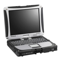
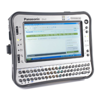
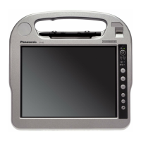
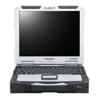
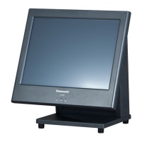
Identifies different model variations of the JS-960 POS Workstation.

Pre-cautionary Measures

Version History

Tracks revisions and changes made to the service manual.

1. Overview of JS-960 Series

1.1. General Features

Highlights key aspects like modular structure and high quality.

1.3. Physical Dimensions

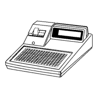
Provides physical dimensions and layout drawings of the POS Workstation.

1.4. I/O Connector Layouts

Illustrates the location and type of all I/O ports on the unit.

1.5. Pin Assignments

Details the pin configurations for various I/O connectors.

1.2. Technical Specifications

Common Specifications

Details general hardware specifications and environmental conditions.

POS Workstation Specifications

Details model-specific hardware specifications for POS workstations.

2. Description of Operation

2.1. System Block Diagrams

Visual representation of the system's interconnected components.

2.2. PCB Component Descriptions

Lists and describes the integrated circuits on the main PCB.

3-Way Installation Options

Ecology and Environmental Features

Highlights the product's environmental friendliness and power saving features.

Design and Maintenance

Compact and User-Friendly Design

Focuses on the compact design and user-friendly aspects of the POS.

Maintenance and Accessibility Features

Details how to access and maintain the POS unit for daily work.

Component Quality and Features

1.3. Physical Dimensions

1.4. I/O Connector Layouts

1.5. Pin Assignment Details

2. Description of Operation

2.1. System Block Diagrams

Visual representation of the system's interconnected components.

2.2. PCB Component Descriptions

3. Test Program (PE Diag)

3.1. Pre-Caution for PE Diag

Important safety and usage notes before running the PE Diag test.

3.3. PE Diag Installation Guide

Step-by-step instructions on how to install the PE Diag software.

3.4. Running PE Diag Diagnostic Tests

3.5. Using the PE Diag Tool Effectively

Motherboard & Component Specification Checks

Verifies BIOS, CPU, DIMM, and SATA specifications against system settings.

1-1. BIOS Version Check

Verifies the system's BIOS version for compatibility.

1-2. BIOS Date Check

Verifies the BIOS release date.

1-3. CPU Type Verification

Confirms the installed CPU type.

1-4. DIMM Capacity Verification

Verifies the installed RAM capacity.

1-5. SATA Drive Checks

2. Model, Serial Number, UTR Verification

Compares system identification data with the nameplate.

3. PE Diag Function Buttons Explained

Explains the controls within the PE Diag software interface.

4. Hardware Monitoring Parameters

4-1. CPU Temperature Monitoring

Monitors the CPU's operating temperature.

4-2. System Temperature Monitoring

Monitors the system's overall temperature.

4-3. CPU Fan Speed Monitoring

Checks the rotational speed of the CPU fan.

4-4. PSU Fan Speed Monitoring

Checks the rotational speed of the Power Supply Unit fan.

4-5. Vcore Voltage Monitoring

Monitors the CPU core voltage.

4-6. +1.5V Voltage Monitoring

Monitors the +1.5V power rail.

4-7. +3.3V Voltage Monitoring

Monitors the +3.3V power rail.

4-8. +5V Voltage Monitoring

Monitors the +5V power rail.

4-9. +12V Voltage Monitoring

Monitors the +12V power rail.

4-10. VBat Voltage Monitoring

Monitors the VBAT voltage.

5. Manual Test Interpretation Guide

Guidance on interpreting results for manual diagnostic tests.

5-1. MSR ISO and JIS Test Procedures

5-3. VFD2L Display and Audio Tests

Tests the 2-line display and speaker functionality.

5-5. LCD Color and SW Tests

Checks the LCD color, backlight, and touch response.

5-7. LED Indicator and Fingerprint Tests

Checks LED blinking and fingerprint scanner functionality.

5-9. Cash Drawer Tests

Tests the cash drawer connectivity and operation.

6. Memory and Auto Test Modes

Performs memory test and explains auto test execution.

7-1. COM Port Loopback Tests

7-2. USB Device Connectivity Test

Verifies USB port functionality with external devices.

7-3. LAN Connectivity Test

Guides testing the network connection using another JS-960Wx.

7-5. LPT Port Loopback Test

Tests the parallel port using a loopback connector.

8. Automated Test Execution

3.6. Diagnostic Configuration File (Diag_Setting.ini)

3.7. Analyzing Diagnostic Logs

4. PCB Information

4.1. Main PCB Schematics

Detailed electrical schematics for the main PCB.

4.1.2. Main PCB Parts Location Diagram

4.1.3. Main PCB Replacement Parts List

List of replaceable parts for the main PCB.

4.2. LCD Relay PCB Information

4.2.1. LCD Relay PCB Schematic Diagram

Electrical schematic for the LCD Relay PCB.

4.2.2. LCD Relay PCB Parts Location

4.2.3. LCD Relay PCB Replacement Parts List

List of replaceable parts for the LCD Relay PCB.

4.3. MB to LCD PCB Interface

4.3.1. MB to LCD PCB Schematic Diagram

Electrical schematic for the MB to LCD PCB.

4.3.2. MB to LCD PCB Parts Location

4.3.3. MB to LCD PCB Replacement Parts List

List of replaceable parts for the MB to LCD PCB.

4.4. LED PCB Information

4.4.1. LED PCB Schematic Diagram

Electrical schematic for the LED PCB.

4.4.2. LED PCB Parts Location

4.4.3. LED PCB Replacement Parts List

List of replaceable parts for the LED PCB.

4.5. 2nd Display PCB Information

4.5.1. 2nd Display PCB Schematic Diagram

Electrical schematic for the 2nd Display PCB.

4.5.2. 2nd Display PCB Parts Location

4.5.3. 2nd Display PCB Replacement Parts List

List of replaceable parts for the 2nd Display PCB.

5. Body Block Overview

5.1. Disassembling Drawings

Illustrates how to disassemble various parts of the POS unit.

5.1.1. Main Body Disassembly

Step-by-step disassembly of the main POS unit body.

5.1.2. LCD Module Disassembly

5.1.3. Stand Disassembly

5.1.4. Rear Display Disassembly

5.1.5. MSR Module Disassembly

5.1.6. 2nd Display Module Disassembly

5.2. Replacement Parts List

6. Troubleshooting Guide: System Issues

No Power, Boot, or Display Problems

Diagnostic steps for critical system startup failures.

Boot Device and HDD Errors

Troubleshooting: Customer Display and DVI Port

Troubleshooting: Interface Connectivity

Troubleshooting: Touch Screen Malfunctions

Troubleshooting: Magnetic Stripe Reader (MSR)

8. Power COM Setting Instructions

1. AC Power Cable Removal

Safety step to disconnect power before proceeding.

2. LCD Module Removal

Procedure for detaching the LCD module.

3. COM1 Cover Removal

4. Setting the COM1 Jumper Plug

Instructions for setting the jumper plug to configure COM1.

9. Mounting and Installation Guide

1. Environmental Setup Precautions

Recommendations for ideal installation environments.

2. POS Installation Procedures

General steps and considerations for installing the POS unit.

2.1. Mounting Bracket Assembly

Instructions for attaching mounting brackets to the POS.

2.2. POS Installation Details

10. Cleaning and Maintenance Procedures

Outer Case and Display Cleaning

Methods for cleaning the plastic outer casing and display.

Dust Filter Cleaning Procedure

Procedure for cleaning the unit's dust filter.

11. Capacitive Touch Screen Usage Notes

12. AMI BIOS Beep Code Reference

Related product manuals