EasyManua.ls Logo

Panasonic JS-960WP0M51 User Manual

Panasonic JS-960WP0M51
149 pages
To Next Page IconTo Next Page
Page #1 background imageLoading...
Page #1 background image
ORDER NO. MSBU1111001C0
G20
Service Manual
JS-960 Series
POS Workstation
List of models
Model No. Display Style Touch Panel CPU
Magnetic
Stripe Reader
Rear
Display
JS-960WSUM51 15 inch LCD Upright Capacitive
Intel® Celero
P4500 1.86 GHz
JS-960WSUM61 15 inch LCD Upright Capacitive
Intel® Core™ i5
520 M 2.4 GHz
JS-960WSUR50 15 inch LCD Upright Resistive
Intel® Celero
P4500 1.86 GHz
JS-960WSUR51 15 inch LCD Upright Resistive
Intel® Celero
P4500 1.86 GHz
12 inch (ISO,
Dark)
JS-960WSUC50 15 inch LCD Upright Capacitive
Intel® Celero
P4500 1.86 GHz
JS-960WSUC51 15 inch LCD Upright Capacitive
Intel® Celero
P4500 1.86 GHz
12 inch (ISO,
Dark)
JS-960WS0M51 15 inch LCD Upright Capacitive
Intel® Celero
P4500 1.86 GHz
12 inch (ISO,
Dark)
Yes
JS-960WSHM51 15 inch LCD Upright Capacitive
Intel® Celero
P4500 1.86 GHz
12 inch (ISO,
Dark)
Yes
JS-960WS0M53 15 inch LCD Upright Capacitive
Intel® Celero
P4500 1.86 GHz
12 inch (ISO,
Dark)
JS-960WS0R50 15 inch LCD Upright Resistive
Intel® Celero
P4500 1.86 GHz
JS-960WS0R51 15 inch LCD Upright Resistive
Intel® Celero
P4500 1.86 GHz
12 inch (ISO,
Dark)
V.1.07 (2013.2.4)
© 2013 Panasonic System Networks Co., Ltd.
A
ll right reserved. Unauthorized copying and
distribution is a violation of law.
Question and Answer IconNeed help?

Do you have a question about the Panasonic JS-960WP0M51 and is the answer not in the manual?

Panasonic JS-960WP0M51 Specifications

General IconGeneral
BrandPanasonic
ModelJS-960WP0M51
CategoryDesktop
LanguageEnglish

Summary

Important Safety Precautions and Warnings

Body Block Components and Disassembly Procedures

Main Body Disassembly Procedure

Explains the step-by-step process for disassembling the main unit of the POS workstation.

LCD Module Disassembly Procedure

Details the procedure for disassembling the LCD module of the POS workstation.

Replacement Parts List for Body Block

Lists all available replacement parts for the body block components.

Maintenance and Accessibility Features

Detailed Technical Specifications for JS-960WS

POS Workstation Specifics

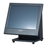
Details CPU, memory, BIOS, OS, display, touch panel, network, and I/O port specifics.

Layout of I/O Ports and Connectors

Main I/O Panel Configurations

Details the layout of ports on the main I/O panel for different configurations.

Detailed Pin Assignments for I/O and Front Panel Connectors

Serial Port (COM1) Pin Assignments

Pin configuration for the 9-pin D-SUB COM1 serial port.

Serial Ports (COM2, COM3) Pin Assignments

Pin configuration for the 9-pin D-SUB COM2 and COM3 serial ports.

Rear Display Serial Port Pin Assignments

Pin assignments for the 8-pin Mini-Din serial port used for the rear display.

Parallel Port Pin Assignments

Pin configuration for the 25-pin D-SUB parallel port.

Pin Assignments for DVI-I and LAN Connectors

DVI-I Connector Pin Assignments

Detailed pinout for the DVI-I connector.

Pin Assignments for USB, Cash Drawer, and SATA/eSATA

On-Board Connector Pin Assignments

Additional Connector Pin Assignments

System Operation Description and Block Diagrams

System Block Diagram (Upright)

Illustrates the system architecture and data flow for the upright POS workstation.

System Block Diagram (VESA Mount)

Illustrates the system architecture and data flow for the VESA mount configuration.

PE Diag Test Program Guide

PE Diag Pre-Cautionary Notes

Important precautions before using the PE Diag test program.

PE Diag Installation Procedure

Step-by-step guide on how to install the PE Diag program.

How to Run the PE Diag Test Program

How to Use the PE Diag Test Program

Motherboard Specification Check

Explains how PE Diag checks motherboard hardware against setting files.

Model No., Serial No., and UTR Check

Procedure for comparing model, serial number, and UTR data.

Hardware Monitor Functionality

Explains how PE Diag monitors hardware status like temperature and voltage.

Manual Test Procedures within PE Diag

MSR (Magnetic Stripe Reader) ISO Test

Procedure for testing the Magnetic Stripe Reader in ISO format.

MSR (Magnetic Stripe Reader) JIS Test

Procedure for testing the Magnetic Stripe Reader in JIS format (Japan).

PE Diag Manual Test Categories

Advanced PE Diag Tests for Connectivity

Automated and Startup Test Procedures in PE Diag

Interpreting PE Diag Log Results

Main PCB Schematics and Diagrams

Main PCB Block Diagram

Visual representation of the main PCB's functional blocks and connections.

Main PCB Schematics, Parts Location, and Replacement List

Main PCB Schematic Diagram

Detailed circuit diagrams for the main PCB.

Main PCB Parts Location Diagram

Illustrates the physical placement of components on the main PCB.

Main PCB Replacement Parts List

List of replaceable parts for the main PCB with part numbers.

LCD Relay PCB Schematics, Parts Location, and Replacement List

MB to LCD PCB Schematics, Parts Location, and Replacement List

LED PCB Schematics, Parts Location, and Replacement List

2nd Display PCB Schematics, Parts Location, and Replacement List

Trouble Shooting Guide for Common Issues

Troubleshooting: No Power, Boot, Start, or Display Issues

Flowchart for diagnosing and resolving power, boot, starting, or display problems.

Troubleshooting: OS Not Found / Remove Disks Error

Flowchart for resolving 'OS not found' or 'remove disks' errors.

Troubleshooting: Customer Display Issues

Flowchart for diagnosing and resolving customer display problems.

Troubleshooting: DVI Port Issues

Flowchart for diagnosing and resolving issues with the DVI port.

Troubleshooting: LAN, Printer, COM, USB Issues

Flowcharts for diagnosing and resolving issues with LAN, Printer, COM, and USB ports.

Troubleshooting: Touch Screen Malfunctions

Flowchart for diagnosing and resolving touch screen non-functional issues.

Troubleshooting: MSR (Magnetic Stripe Reader) Issues

Flowchart for diagnosing and resolving issues with the MSR.

JS-960WS Power COM Setting Instruction

How to Mount JS-960WP on Wall and Under Counter

Capacitive Touch Screen Usage and Care Notice

AMI BIOS Beep Codes for Error Diagnosis

Related product manuals