EasyManua.ls Logo

Panasonic KX-A142RUS User Manual

Panasonic KX-A142RUS
90 pages
To Next Page IconTo Next Page
Page #1 background imageLoading...
Page #1 background image
© 2003 Panasonic Communications Co., Ltd. All
rights reserved. Unauthorized copying and
distribution is a violation of law.
KX-TCD410RUM
KX-TCD410RUS
KX-TCD412RUM
KX-TCD412RUS
KX-A141RUM
KX-A141RUS
KX-A142RUM
KX-A142RUS
Digital Cordless Phone
Metalic Gray Version
Silver Version
(for Russia)
Telephone Equipment
ORDER NO. KM40306109C3

Table of Contents

Question and Answer IconNeed help?

Do you have a question about the Panasonic KX-A142RUS and is the answer not in the manual?

Panasonic KX-A142RUS Specifications

General IconGeneral
BrandPanasonic
ModelKX-A142RUS
CategoryTelephone
LanguageEnglish

Summary

Specifications and Model Configuration

2 FOR SERVICE TECHNICIANS

4 BATTERY MANAGEMENT

4.1. Battery Installation and Charging

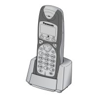
Instructions for installing and charging rechargeable batteries for the handset.

6 SYSTEM SETTINGS

6.3. PIN Code Configuration and Reset

Procedures for setting, changing, and resetting base unit and handset PIN codes.

6.3.3. Reset Base Unit PIN to Default (0000)

Procedure to reset the base unit PIN when no handset is registered.

7 DISPLAY INFORMATION

7.2. Troubleshooting Before Service

Guide on initial troubleshooting steps before contacting support or service.

8 OPERATIONAL PROCEDURES

8.5. Phonebook Management

Detailed guide on storing, editing, clearing, and dialing using the phonebook.

9 DISASSEMBLY INSTRUCTIONS

11 TROUBLESHOOTING GUIDE

11.1. Power Supply Checks

Diagnostic steps to check power issues for the base unit and handset.

11.2. Battery Charge Verification

Procedures to verify battery charging status for base, handset, and charger units.

11.3. Link Establishment Checks

Diagnostic steps to check the communication link between base unit and handset.

12 BASE UNIT CHECK PROCEDURES

13 HANDSET CHECK PROCEDURES

14 ADJUSTMENTS (BASE UNIT & CHARGER UNIT)

14.1. Base Unit Adjustments and Confirmations

Detailed procedures for adjusting and confirming various parameters on the base unit.

14.1.(H) Transmitted Power Confirmation

Checks transmitted power output and DECT tester settings.

14.1.(I) Modulation Check and Adjustment

Verifies and adjusts modulation parameters like B-Field.

14.1.(N) Receive Audio Check and Adjustment

Checks and adjusts audio input levels and distortion for received signals.

14.1.(O) Transmit Audio Check and Adjustment

Checks and adjusts audio output levels and distortion for transmitted signals.

14.2. Base Unit Adjustment Standards

Diagrams showing equipment connection points for base unit adjustments.

14.3. Charger Unit Adjustment

Procedure for performing charging check on the charger unit.

15 ADJUSTMENTS (HANDSET)

15.1. Handset Adjustments and Confirmations

Detailed procedures for adjusting and confirming various parameters on the handset.

15.1.(I) Transmitted Power Confirmation

Confirms transmitted power output and DECT tester settings.

15.1.(J) Modulation Check and Adjustment

Verifies and adjusts modulation parameters like B-Field.

15.1.(O) Receive Audio Check and Confirmation

Checks and confirms audio input levels and distortion for received signals.

15.2. Handset Adjustment Standards

Diagrams showing equipment connection points for handset adjustments.

16 RF SPECIFICATION

16.1. Base Unit RF Specifications

Lists TX power, modulation, frequency offset, RX sensitivity, timing accuracy, and RSSI.

16.2. Handset RF Specifications

Lists TX power, modulation, frequency offset, RX sensitivity, timing accuracy, and RSSI.

17 HANDSET SPEAKER CHECK

19 BLOCK DIAGRAM (BASE UNIT)

20 CIRCUIT OPERATION (BASE UNIT)

20.2. Power Supply Circuit

Explanation of how power is supplied to various components from the AC adapter.

21 BLOCK DIAGRAM (HANDSET)

22 CIRCUIT OPERATION (HANDSET)

22.3. Handset Charge Circuit

Description of the charging circuit operation for the handset.

22.4. Battery Low/Power Down Detection

How the handset detects low battery voltage and power down conditions.

23 CIRCUIT OPERATION (CHARGER UNIT)

25 CPU DATA (BASE UNIT)

26 CPU DATA (HANDSET)

27 EEPROM LAYOUT (BASE UNIT)

27.3. Base Unit EEPROM Contents and Settings

Lists EEPROM addresses, default values, names, and descriptions for base unit settings.

28 EEPROM LAYOUT (HANDSET)

28.3. Handset EEPROM Contents and Settings

Lists EEPROM addresses, default values, names, and descriptions for handset settings.

29 HOW TO REPLACE FLAT PACKAGE IC

34 TERMINAL GUIDE OF THE ICs, TRANSISTORS, AND DIODES

35 REPLACEMENT PARTS LIST

35.1. Base Unit Replacement Parts

Comprehensive list of replacement parts for the base unit, including ICs, transistors, diodes, and coils.

35.2. Handset Replacement Parts

Comprehensive list of replacement parts for the handset, including ICs, transistors, diodes, and coils.

35.3. Charger Unit Replacement Parts

Comprehensive list of replacement parts for the charger unit, including ICs, transistors, and diodes.

35.5. Fixtures and Tools

36 SCHEMATIC DIAGRAM (BASE UNIT)

37 SCHEMATIC DIAGRAM (HANDSET)

38 SCHEMATIC DIAGRAM (CHARGER UNIT)

39 CIRCUIT BOARD (BASE UNIT)

40 CIRCUIT BOARD (HANDSET)

41 CIRCUIT BOARD (CHARGER UNIT)

Related product manuals