EasyManua.ls Logo

Panasonic KX-A141RUM User Manual

Panasonic KX-A141RUM
90 pages
To Next Page IconTo Next Page
Page #1 background imageLoading...
Page #1 background image
© 2003 Panasonic Communications Co., Ltd. All
rights reserved. Unauthorized copying and
distribution is a violation of law.
KX-TCD410RUM
KX-TCD410RUS
KX-TCD412RUM
KX-TCD412RUS
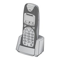
KX-A141RUM
KX-A141RUS
KX-A142RUM
KX-A142RUS
Digital Cordless Phone
Metalic Gray Version
Silver Version
(for Russia)
Telephone Equipment
ORDER NO. KM40306109C3

Table of Contents

Question and Answer IconNeed help?

Do you have a question about the Panasonic KX-A141RUM and is the answer not in the manual?

Panasonic KX-A141RUM Specifications

General IconGeneral
BrandPanasonic
ModelKX-A141RUM
CategoryTelephone
LanguageEnglish

Summary

2 FOR SERVICE TECHNICIANS

4 BATTERY

Details battery installation, charging, life, and replacement procedures.

7 DISPLAY

7.2. Before Requesting Help (Troubleshooting)

Provides a troubleshooting guide for common issues.

9 DISASSEMBLY INSTRUCTIONS

11 TROUBLESHOOTING GUIDE

11.1. Check Power

Guide for diagnosing power-related issues in base unit and handset.

11.2. Check Battery Charge

Procedure for verifying battery charging status for base, handset, and charger.

11.3. Check Link

Steps to diagnose and troubleshoot base unit and handset link issues.

12 CHECK PROCEDURE (BASE UNIT)

12.1. Preparation

Lists required equipment and JIGs/PC setup for base unit checks.

12.2. PC Setting

Details connection and PC configuration for base unit checks.

13 CHECK PROCEDURE (HANDSET)

13.1. Preparation

Lists required equipment and JIGs/PC setup for handset checks.

13.2. PC Setting

Details connection and PC configuration for handset checks.

14 ADJUSTMENTS (BASE UNIT AND CHARGER UNIT)

14.1. Adjustment (Base Unit)

Procedures for adjusting and confirming parameters for the base unit.

14.2. Adjustment Standard (Base Unit)

Shows component view and connection diagrams for base unit adjustments.

14.3. Adjustment (Charger Unit)

Procedure for charging check on the charger unit.

15 ADJUSTMENTS (HANDSET)

15.1. Adjustment

Procedures for adjusting and confirming parameters for the handset.

15.2. Adjustment Standard (Handset)

Shows component view and connection diagrams for handset adjustments.

16 RF SPECIFICATION

16.1. Base Unit

Lists RF specifications for the base unit.

16.2. Handset

Lists RF specifications for the handset.

19 BLOCK DIAGRAM (BASE UNIT)

20 CIRCUIT OPERATION (BASE UNIT)

21 BLOCK DIAGRAM (HANDSET)

23 CIRCUIT OPERATION (CHARGER UNIT)

25 CPU DATA (BASE UNIT)

26 CPU DATA (HANDSET)

29 HOW TO REPLACE FLAT PACKAGE IC

34 TERMINAL GUIDE OF THE ICs, TRANSISTORS AND DIODES

35 REPLACEMENT PARTS LIST

35.1. Base Unit

Lists replacement parts for the base unit, including PC board components.

35.2. Handset

Lists replacement parts for the handset, including PC board components.

35.3. Charger Unit

Lists replacement parts for the charger unit, including PC board components.

36 SCHEMATIC DIAGRAM (BASE UNIT)

37 SCHEMATIC DIAGRAM (HANDSET)

38 SCHEMATIC DIAGRAM (CHARGER UNIT)

39 CIRCUIT BOARD (BASE UNIT)

40 CIRCUIT BOARD (HANDSET)

41 CIRCUIT BOARD (CHARGER UNIT)

Related product manuals