(Example)
Bit No. DIS/DTC DCS
1 Transmitter - T.2 operation
2 Receiver - T.2 operation Receiver - T.2 operation
3 T.2 IOC = 176 T.2 IOC = 176
4 Transmitter - T.3 operation
5 Receiver - T.3 operation Receiver - T.3 operation
6 Reserved for future T.3 operation features.
7 Reserved for future T.3 operation features.
8 Reserved for future T.3 operation features.
9 Transmitter - T.4 operation
10 Receiver - T.4 operation Receiver - T.4 operation
11, 12
(0, 0)
(0, 1)
(1, 0)
(1, 1)
Data signaling rate
V.27 ter fall back mode
V.27 ter
V.29
V.27 ter and V.29
Data signaling rate
2400 bit/s, V.27 ter
4800 bit/s, V.27 ter
9600 bit/s, V.29
7200 bit/s, V.29
13 Reserved for the new modulation system.
14 Reserved for the new modulation system.
15 Vertical resolution = 7.7 line/mm Vertical resolution = 7.7 line/mm
16 Two-dimensional coding capability Two-dimensional coding
17, 18
(0, 0)
(0, 1)
(1, 0)
(1, 1)
Recording width capabilities
1728 picture elements along scan line length of
215 mm ± 1%
1728 picture elements along scan line length of
215 mm ± 1% and
2048 picture elements along scan line length of
255 mm ± 1% and
2432 picture elements along scan line length of
303 mm ± 1%
1728 picture elements along scan line length of
215 mm ± 1% and
2048 picture elements along scan line length of
255 mm ± 1%
Invalid
Recording width
1728 picture elements along scan line length of
215 mm ± 1%
2432 picture elements along scan line length of
303 mm ± 1%
2048 picture elements along scan line length of
255 mm ± 1%
Invalid
19, 20
(0, 0)
(0, 1)
(1, 0)
(1, 1)
Maximum recording length capability
A4 (297 mm)
Unlimited
A4 (297 mm) and B4 (364 mm)
Invalid
Maximum recording length
A4 (297 mm)
Unlimited
B4 (364 mm)
Invalid
Signal.....DCS (Digital Command Signal)
Identification Signal Format.....X1000001
Function:
Notifies the capacity of the receiving machine obtained at DIS and announces the transmission mode of the sender. The added
data signals are as follows.
(Example)
Bit No. DIS/DTC Standard setting DCS
21, 22, 23
(0, 0, 0)
(0, 0, 1)
(0, 1, 0)
(1, 0, 0)
(0, 1, 1)
(1, 1, 0)
(1, 0, 1)
(1, 1, 1)
Minimum scan line time capability of the receiver
20 ms at 3.85 l/mm: T7.7 = T3.85
40 ms at 3.85 l/mm: T7.7 = T3.85
10 ms at 3.85 l/mm: T7.7 = T3.85
5 ms at 3.85 l/mm: T7.7 = T3.85
10 ms at 3.85 l/mm: T7.7 = 1/2 T3.85
20 ms at 3.85 l/mm: T7.7 = 1/2 T3.85
40 ms at 3.85 l/mm: T7.7 = 1/2 T3.85
0 ms at 3.85 l/mm: T7.7 = T3.85
Minimum scan line time
20 ms
40 ms
10 ms
5ms
0ms
24 Extend field 1 Extend field
25 2400 bit/s handshaking 0 2400 bit/s handshaking
26 Uncompressed mode 0 Uncompressed mode
27 Error correction mode 0 Error correction mode
28 Set to "0". 0 Frame size 0 = 256 octets 1 = 64 octets
29 Error limiting mode 0 Error limiting mode
30 Reserved for G4 capability on PSTN 0 Reserved for G4 capability on PSTN
31 Unassigned 0
32 Extend field 1 Extend field
33
(0)
(1)
Validity of bits 17, 18
Bits 17, 18 are valid
Bits 17, 18 are invalid
0 Recording width
Recording width indicated by bits 17, 18
Recording width indicated by this field bit
information
126
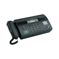
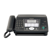
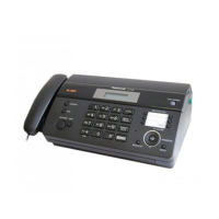
KX-FT63BX / KX-FT63BX-W
 Loading...