EasyManua.ls Logo

Panasonic KX-FT931LA-B

Panasonic KX-FT931LA-B
173 pages
To Next Page IconTo Next Page
Loading...
© 1995 Matsushita Electric Industrial Co., Ltd. All
rights reserved. Unauthorized copying and distribu-
tion is a violation of law.
Order No.KMF0605960CE
Personal Facsimile
KX-FT931LA-B
B: Black Version
(for Latin America)

Table of Contents

Question and Answer IconNeed help?

Do you have a question about the Panasonic KX-FT931LA-B and is the answer not in the manual?

Panasonic KX-FT931LA-B Specifications

General IconGeneral
Paper SizeA4, Letter, Legal
MemoryUp to 28 pages
Printing TechnologyThermal Transfer
Copier FunctionYes
Caller IDYes
Answering Machine InterfaceYes
Out-of-Paper ReceptionYes
Paper Capacity50 sheets
Power SupplyAC 220-240 V, 50/60 Hz
Transmission Speed15 seconds per page
Paper HandlingPlain Paper
Automatic Document Feeder (ADF)Yes
Fax Resolution203 x 98 dpi
Telephone IndexYes
TypePlain Paper Fax

Summary

Safety Precautions

For Service Technicians

Precautions for technicians to prevent malfunctions and damage.

Suggested PBF Sloder

Recommendations for lead-free solder wire sizes for service.

AC Caution

Personal Safety Precautions

Moving Sections of the Unit

Warning about potential hazards from moving parts like rollers and gears.

Live Electrical Sections

Warning about live electrical sections and the need to unplug power.

Service Precautions

Precautions to Prevent Damage from Static Electricity

Measures to prevent static electricity damage to electronic components.

Warning

About Lead Free Solder (PbF: Pb free)

Information on lead-free solder properties and handling precautions.

Insulation Resistance Test

Steps for performing an insulation resistance test for shock hazard prevention.

Battery Caution

Cautionary notes regarding lithium battery replacement and disposal.

Specifications

GeneralIntroduction

Optional Accessories

List of optional accessories available for the unit.

Translation Lists

Lists of terms translated into different languages for messages.

Error Message (Display)

Features

General

Overview of general features like LCD display and ADF.

Facsimile

Features related to facsimile operation like broadcast and resolution.

Integrated Telephone System

Features of the integrated telephone system, including redial and phonebook.

Enhanced Copier Function

Details about the enhanced copier functionality.

Technical Descriptions

Connection Diagram

Diagram illustrating the connection points between different boards and components.

General Block Diagram

General Block Diagram

Control Section

ASIC (IC1)

Description of the ASIC's functions and pin distribution.

ASIC (IC1)

ASIC (IC1)

Flash Memory (IC2)

Dynamic RAM (IC4)

Reset Circuit (Watch dog timer)

RTC Back up Circuit

Supervision Circuit for the Thermal Head Temperature

Facsimile Section

Image Data Flow During Facsimile Operation

Flow of image data during copy, transmission, and reception operations.

Block Diagram

Thermal Head

Scanning Block

Stepping Motor Drive Circuit

Sensors and Switches

Motor Position Sensor

Recording Paper Sensor (SW1)

Hook Switch (SW2)

Jam Sensor (SW3)

Document Top Sensor (SW39)

Document Set Sensor (SW38)

Modem Section

Modem Section Function

Facsimile Standards

Communication and Compression Technology

G3 Communication Signals (T. 30 Binary Process)

Exchange of control signals between sending and receiving facsimile machines.

Communication and Compression Technology

Communication and Compression Technology

Redundancy Compression Process Coding Mode

Modem Circuit Operation

NCU Section

General

Components of the NCU section, including bell detection and dial circuits.

Bell Detection Circuit

Operation of the bell detection circuit and signal waveforms.

ONOFF Hook Circuit

How the ON/OFF hook circuit controls the line relay.

Pulse Dial Circuit

Operation of the pulse dial circuit for making and breaking states.

Line Amplifier and Side Tone Circuits

Calling Line Identification Circuit

Function

Compatibility with Caller ID service and signal format.

Circuit Operation

How the Caller ID signal is processed by the modem.

Calling Line Identification Circuit (DTMF)

ITS (Integrated Telephone System) and Monitor Section

General

Overview of ITS operation performed by modem and ASIC.

Handset Circuit

Control of conversation over the handset, including signal path.

Monitor Circuit for Each Signals

Circuit that monitors various tones like DTMF and alarm tones.

Remote Receiving

Parallel connection DTMF signal for TEL mode and FAX receiving.

Circuit Diagram

Operation Board Section

LCD Section

Power Supply Board Section

Power Supply Board Section

Power Supply Board Section

Location of Controls and Components

Overview

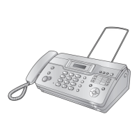
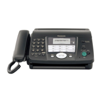
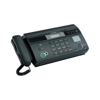
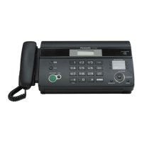
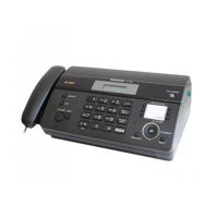
Diagram showing the location of external controls and components.

Control Panel

Installation Instructions

Installation Space

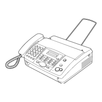
Recommended space and environmental conditions for unit installation.

Connections

Instructions for connecting the power cord and telephone line.

Installing the Recording Paper

Operation Instructions

Setting Your Logo

How to set a custom logo to be printed on transmitted pages.

Setting Your Logo

Test Mode

DTMF Single Tone Transmit Selection

Button Code Table

Print Test Pattern

Service Mode

Programming and Lists

Overview of User Mode and Service Mode for programming and testing.

Service Function Table

Memory Clear Specification

The Example of the Printed List

User Mode (Example of a printed out list)

Example of a printed user mode list showing default values.

Service Mode Settings (Example of a printed out list)

History (Example of a printed out list)

Descriptions of the History Report

Troubleshooting Guide

Troubleshooting summary

Summary of troubleshooting steps and general precautions.

Error Messages-Display

Error Messages Report

Journal Report

How to print and interpret the journal report for problem diagnosis.

Special service journal reports

Journal 2

Journal 3

Communication Section

Defective Facsimile Section

Transmit Problem

Troubleshooting flowchart for issues encountered during transmission.

Sometime there is a transmit problem

Receive Problem

The unit can copy, but cannot transmitreceive

The unit can copy, but cannot either transmitreceive long distance or international communications

The unit can copy, but cannot either transmitreceive long distance or international communications

The unit can copy, but the transmission and reception image are incorrect

How to record fax signal by using PC

Remote Programming

Entering the Remote Programming Mode and Changing Service Codes

Procedure to enter remote programming mode and change service codes via phone.

Program Mode Table

Program Mode Table

Troubleshooting Details

Outline

Overview of the troubleshooting process for recovering quality and reliability.

Starting Troubleshooting

Initial steps to determine the symptom and select the troubleshooting method.

Troubleshooting Items

Simple Check List

A checklist for basic functional checks of the unit's operation.

ADF (Auto Document Feed) Section

No Document Feed

Troubleshooting flowchart for issues where no document is fed by the ADF.

Document Jam

Multiple Feed

Skew

Image is Distorted (When printing)

Black or White Vertical Lines Appear

Skewed Receiving Image

When Coping or Printing, an Abnormal Sound is Heard from the Unit

Digital Board Section

Digital Block Diagram

Digital Block Diagram

Digital Block Diagram

Check the Status of the Digital Board

Check the Status of the Digital Board

NG Example

Analog Board Section

Signal Route

Detailed signal routes for testing analog parts of the unit.

Defective ITS (Integrated Telephone System) Section

Power Supply Board Section

Key components for troubleshooting

Key components to check first for power supply board troubleshooting.

Troubleshooting Flow Chart

Broken Parts Repair Details

Operation Panel Section

No Key Operation

Troubleshooting steps when keys on the operation panel do not work.

No LCD Indication

Troubleshooting steps when the LCD display shows no indication.

Sensor Section

Check the Document Sensor (SW39)

Steps to check the document sensor for proper operation.

Check the Read Position Sensor (SW38)

Steps to check the read position sensor for proper operation.

CIS (Contact Image Sensor) Section

Thermal Head Section

Service Fixture & Tools

Disassembly and Assembly Instructions

Disassembly Flowchart

Flowchart outlining the steps for disassembling the unit's upper cabinet.

Upper Cabinet Section

Steps for disassembling the upper cabinet section of the unit.

Lower Cabinet Section

Disassembly Procedurel

How to Remove the Operation Panel Block

Step-by-step guide to remove the operation panel block.

How to Remove the Operation Board, LCD and Platen Roller

How to Remove the Separation Holder and Document Feed Support

How to Remove the Image Sensor (CIS) and Feed Roller

How to Remove the Lock Lever and Thermal Head

How to Remove the Bottom Frame

How to Remove the Analog Board, Digital Board, Power Supply Board and Power Cord

How to Remove the Gear Block and Separation Roller

How to Remove the Motor of Gear Block

Installation Position of the Lead Wires

Maintenance

Maintenance Items and Componet Locations

List of maintenance check items and their locations.

Maintenance List

Maintenance Cycle

Gear Section

Mode Selection

How the gear mechanism selects operating modes (Transmit, Receive, Copy).

Mode Operation

TX Mode

Gear operation for the transmit mode.

RX Mode

Gear operation for the receive mode.

Copy Mode

Reverse Mode

Mechanical Movements in the Main Operations

Idle Status

Motor rotation and switch state during idle status.

Scanning

Printing

Copying

Jams

Recording Paper Jams

Steps for clearing recording paper jams.

Document Jams - Sending

Steps for clearing document jams during sending.

Cleaning

Document Feeder Cleaning

Procedure for cleaning the document feeder rollers and glass.

Thermal Head Cleaning

Procedure for cleaning the thermal head to remove dust and smudges.

Miscellaneous

Terminal Guide of the ICs, Transistors and Diodes

Terminal identification for ICs, transistors, and diodes on the digital board.

Terminal Guide of the ICs, Transistors and Diodes

Digital Board

Terminal identification for ICs, transistors, and diodes on the digital board.

Analog Board

Terminal identification for components on the analog board.

Operation Board

Terminal identification for components on the operation board.

Power Supply Board

How to Replace the Flat Package IC

Preparation

Tools and materials required for replacing flat package ICs.

Flat Package IC Removal Procedure

Steps for removing flat package ICs from the PCB.

Flat Package IC Installation Procedure

Steps for installing new flat package ICs onto the PCB.

Bridge Modification Procedure

Test Chart

ITU-T No.1 Test Chart

ITU-T No.1 test chart used for facsimile testing.

ITU-T No.2 Test Chart

Schematic Diagram

Digital Board

Schematic diagram of the digital board.

Analog Board

Operation Board

Power Supply Board

Printed Circuit Board

Digital Board

Component layout view of the digital printed circuit board.

Analogue Board

Component View

Component layout view of the analog printed circuit board.

Operation Board

Component View

Component layout view of the operation board.

Power Supply Board

Appendix Information of Schematic Diagram

Exploded View and Replacement Parts List

Cabinet, Mechanical and Electrical Parts Location

Illustrated locations of parts in the operation panel section.

Upper Cabinet Section

Lower Cabinet Section

Gear Block Section

Screws

Accessories and Packing Materials

Replacement Parts List

Cabinet and Mechaical Parts

List of replacement parts for the operation panel section.

Gear Block Section

Accessories and packing materials

Digital Board Parts

Analog Board Parts

Operation Board Parts

Power Supply Board Parts

Fixtures and Tools

Related product manuals