Do you have a question about the Panasonic KX-TG1032S and is the answer not in the manual?
Precautions for service technicians to prevent malfunctions and ensure safety during repair work.
Warnings regarding the safe handling and replacement of batteries to prevent explosion risks.
Information on lead-free solder used in manufacturing and its implications for service and repair.
A block diagram illustrating the main components and connections of the base unit.
Explanation of the operational principles and functions of the base unit's circuits.
Details on how power is supplied to the various components within the base unit.
Description of the circuit responsible for handling telephone line signals and connections.
Explanation of the circuits responsible for transmitting and receiving radio signals.
A block diagram showing the main components and interconnections within the handset.
Explanation of the operational principles and functions of the handset's circuits.
Details on the power supply and reset functions within the handset.
Explanation of the circuit responsible for charging the handset's battery.
Description of the circuit that monitors battery status and initiates power down.
Information about the speakerphone functionality and its use for ring alarms.
Explanation of the operational principles and functions of the charger unit.
Details on how power is supplied to the charger unit and its components.
Trace of signal paths for various functions between the base unit and handset.
Identification and description of the physical controls on the base unit and handset.
Explanation of the items and information displayed on the handset screen.
Step-by-step guide for connecting and setting up the base unit.
Instructions for connecting the unit if a DSL service is used, including noise filter recommendations.
Step-by-step guide for connecting the AC adaptor to the handset charger.
Information on battery installation, replacement, and important usage notes.
Instructions on how to charge the handset batteries and indicators for charging status.
Description of the battery level indicators displayed on the handset.
Information on battery operating times and factors affecting performance.
Guide to customizing various features and settings via the handset menu.
Procedure for registering a handset to the base unit, including adding or removing units.
Instructions on how to copy phonebook entries from one handset to another.
A list of display messages indicating problems and their corresponding causes and solutions.
A guide to diagnosing and resolving common operational issues.
Troubleshooting specific issues related to the Caller ID feature, including display and dialing problems.
Troubleshooting common problems with the answering system, such as listening to messages or recording issues.
Instructions for accessing and using the engineering mode for advanced settings and diagnostics on the base unit.
List and explanation of frequently accessed items in the base unit's service mode.
Instructions for entering and using the engineering mode on the handset.
List and explanation of frequently accessed items in the handset's service mode.
Procedure for copying phonebook data between handsets during repair scenarios.
Steps to reset the unit to factory settings, clearing user configurations and data.
A flowchart to guide users through diagnosing and resolving common operational issues.
Procedures for checking power supply issues in both the base unit and handset.
Steps to verify battery charging status and related circuits for base unit, handset, and charger.
Procedures for checking the wireless link between the base unit and handset.
Specific checks for establishing a link with the handset unit.
Procedures for checking and identifying potential issues within the radio frequency components.
A flowchart detailing the steps for performing radio frequency checks on the unit.
A table outlining specific checks and expected results for RF part diagnostics.
Instructions for testing the operational range of the wireless communication link.
Visual representation and analysis of signal waveforms at the RF-BBIC interface.
Procedure to verify the handset's ability to transmit signals correctly.
Procedure to verify the handset's ability to receive signals correctly.
Steps to check the functionality of the Caller ID feature.
Procedures for checking the bell reception signal in both the base unit and handset.
Guide for checking the functionality of the Telephone Answering Machine (TAM) system.
Step-by-step troubleshooting based on symptoms observed in the base unit and charger.
Step-by-step troubleshooting based on symptoms observed in the handset.
Detailed instructions on safely removing and replacing flat package ICs using basic tools.
Steps for correctly installing a flat package IC onto the circuit board.
Method for removing solder bridges formed during component installation.
Detailed instructions for replacing LLP ICs, including preparation and removal techniques.
Steps for correctly installing an LLP IC, including soldering the bottom pad and pins.
Method for removing solder bridges that may occur after soldering the bottom of an LLP IC.
General instructions for disassembling the base unit, including screw and wire removal.
Step-by-step guide for disassembling the handset unit, including opening the cabinet and removing components.
Instructions for disassembling the charger unit, including removing screws, hooks, and the cabinet cover.
Detailed procedure for replacing the LCD screen on the handset, including heat sealing.
Instructions for setting up the JIG and PC for measurements and adjustments on the base unit.
Guide to configuring batch files for automated settings and commands during JIG setup.
A list of frequently used commands for interacting with the unit during JIG setup and testing.
Standards and procedures for performing adjustments on the base unit after connecting simulator equipment.
A diagram showing the flow solder side of the base unit's PCB with test points and connections.
Standards and procedures for performing adjustments on the charger unit after connecting simulator equipment.
Instructions for setting up the JIG and PC for measurements and adjustments on the handset.
Guide to configuring batch files for automated settings and commands during handset JIG setup.
A list of frequently used commands for interacting with the handset during JIG setup and testing.
Standards and procedures for performing adjustments on the handset after connecting simulator equipment.
Minimum adjustments required after replacing ICs or crystals in the base unit and handset.
Procedure for testing the functionality of the handset's speaker and receiver using a digital voltmeter.
A table listing the transmit and receive frequencies for each channel in MHz.
General notes and important safety notices regarding the schematic diagrams provided in the manual.
Detailed schematic diagram of the main circuit board for the base unit.
Schematic diagram illustrating the operational control circuits of the base unit.
Detailed schematic diagram of the circuit board for the handset.
Schematic diagram showing the circuit layout of the charger unit.
Component layout diagram for the main circuit board of the base unit.
Diagram of the flow solder side of the base unit's main circuit board, showing component placement.
Component layout diagram for the operational control circuit board of the base unit.
Component layout diagram for the circuit board of the handset.
Diagram of the flow solder side of the handset circuit board, showing component placement.
Component layout diagram for the circuit board of the charger unit.
Diagram of the flow solder side of the charger unit circuit board, showing component placement.
Pin details and functions for the CPU (BBIC) component in the base unit.
Pin details and functions for the CPU (BBIC) component in the handset.
Visual guide to the terminal pinouts for various ICs, transistors, and diodes used in the unit.
Exploded view of the base unit showing cabinet and electric parts, with reference numbers.
Exploded view of the handset showing cabinet and electric parts, with reference numbers.
Exploded view of the charger unit showing cabinet and electric parts, with reference numbers.
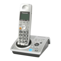
List and illustration of accessories and packing materials included with the KX-TG1032S model.
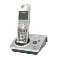
List and illustration of accessories and packing materials included with the KX-TG1033S model.
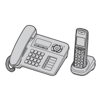
List and illustration of accessories and packing materials included with the KX-TG1034S model.
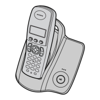
List and illustration of accessories and packing materials included with the KX-TGA101S model.
Comprehensive list of replacement parts, including part numbers and descriptions for the base unit.
List of replacement parts for the operational PC board of the handset.
List of replacement cabinet and electrical parts for the handset.
List of replacement parts for the charger unit's cabinet and electrical components.
List of replacement parts for the main PC board of the charger unit.
List of accessories and packing materials for models KX-TG1033S, KX-TG1034S, and KX-TGA101S.
List of screw types used in the unit assembly.
List of fixtures and tools required for servicing, including JIGs and soldering equipment.
| Type | Cordless Telephone |
|---|---|
| Number of Handsets | 2 |
| Frequency | 1.9 GHz |
| Caller ID | Yes |
| Standby Time | 120 hours |
| Range | Up to 1000 feet |
| Speakerphone | Yes |
| Intercom | Yes |
| Call Waiting | Yes |
| Answering Machine | No |
| Backlit Display | Yes |
| Color | Silver |
| Phonebook Capacity | 50 |
| Expandable | Yes |