29
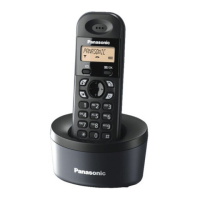
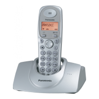
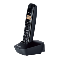
KX-TG1381HKH/KX-TG1381HKV/KX-TG1381HKW/KX-TG1382HKH/KX-TGA131HMH/KX-TGA131HMV/KX-TGA131HMW
(F)* Hookswitch Check with
DC Characteristics
- 1. Connect J1 (Telephone Socket) to Tel-simulator which is connected with 600
Ω.
2. Set line voltage to 48V at on-hook condition and line current to 40mA at off-
hook condition of normal telephone.
3. Execute the command “hookoff”.
4. Confirm that the line current is 40mA ± 5mA.
5. Execute the command “hookon”.
6. Confirm that the line current is 0mA + 2mA.
Career mod-
ule. C30, C31,
D2, Q3, Q2,
R26, R22,
R18, R15
(G)* DTMF Generator Check - 1. Connect J1 (Telephone Socket) to DTMF tester.
2. Execute the command “hookoff” and “dtmf_up”.
3. Confirm that the high frequency (1477.06Hz) group is -7.5 ± 2 dBm.
4. Execute the command “dtmf_lo”.
5. Confirm that the low frequency (852.05Hz) group is-9.5 ± 2 dBm.
Career mod-
ule, R2, C4,
C5, R7, R9,
R10, C9, R11,
R13, R12, R6,
Q1, D10, D1,
Q3, R26, R22,
Q2, R18, D2,
C30, C31
(H)* Transmitted Power Con-
firmation
- Remove the Antenna before starting steps from 1 to 5.
1. Configure the DECT tester (CMD60) as follows;
<Setting>
• Test mode: FP
• Traffic Channel: 5
• Traffic Slot: 4
• Mode: Loopback
• PMID: 00000
2. Execute the command “testmode”.
3. Initiate connection from DECT tester. (“set up connect”)
4. Execute the command “ANT”.
5. Confirm that the NTP value at ANT is 14dBm ~ 20dBm.
Career mod-
ule, C4, C6,
C2, C3, C25,
C8, C1, C12,
C13, C7, L1,
L2, C18, C19,
D1, C17, R2,
C23, BASE
module. R43,
R44, L2, C38,
C42, D6, C39,
C41
(I)* Modulation Check and
Adjustment
ANT Follow steps 1 to 3 of (H).
4. Confirm that the B-Field Modulation is 340kHz/div ~ 402kHz/div using data
type Fig31.
5. Adjust the B-Field Modulation if required. (Execute the command “readmod”
and “wrtmod xx”, where xx is the value.)
Career mod-
ule, C4, C6,
C2, C3, C25,
C8, C1, C12,
C13, C7, L1,
L2, C18, C19,
D1, C17, R2,
C23, BASE
module. R43,
R44, L2, C38,
C42, D6, C39,
C41
(J)* Frequency Offset Check - Follow steps 1 to 3 of (H).
4. Confirm that the frequency offset is -50kHz ~ +50kHz.
Career mod-
ule, C4, C6,
C2, C3, C25,
C8, C1, C12,
C13, C7, L1,
L2, C18, C19,
D1, C17, R2,
C23, BASE
module. R43,
R44, L2, C38,
C42, D6, C39,
C41
(K)* Sensitivity Receiver
Confirmation
- Follow steps 1 to 3 of (H).
4. Set DECT tester power to -84dBm.
5. Confirm that the BER is < 1000ppm.
Career mod-
ule, C4, C6,
C2, C3, C25,
L3, L4, C15,
C20, R1, C21,
D1, C17, C20,
R1, C21, D1,
C17, BASE
module, R43,
R44, L2, C38,
C42, D6, C39,
C41
Items Adjustment
Point
Procedure Check or
Replace Parts

 Loading...