35
9.1.3. Disassembly Procedure
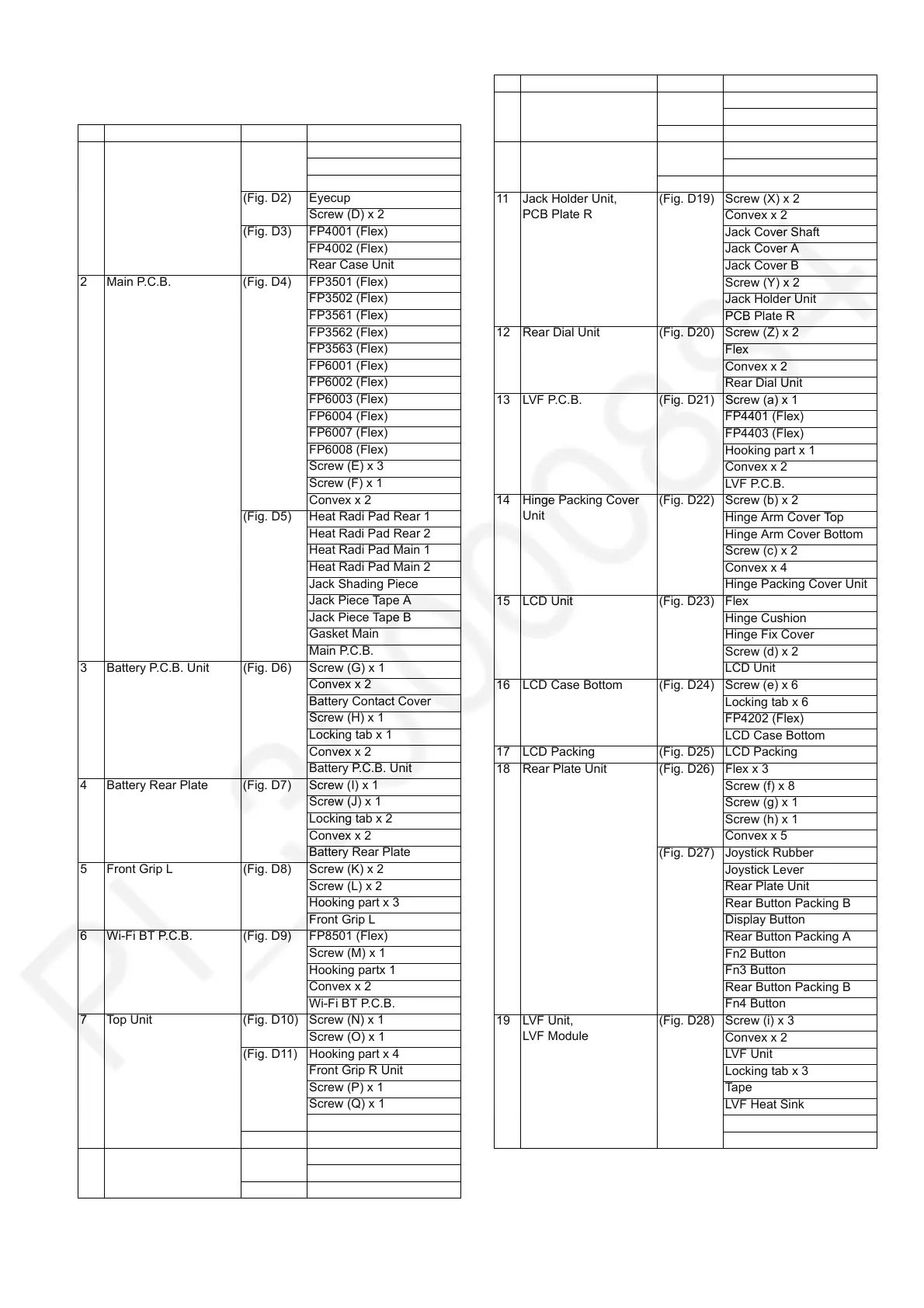
No. Item Fig. Removal
1 Rear Case Unit (Fig. D1) Screw (A) x 3
Screw (B) x 2
Screw (C) x 2
(Fig. D2) Eyecup
Screw (D) x 2
(Fig. D3) FP4001 (Flex)
FP4002 (Flex)
Rear Case Unit
2 Main P.C.B. (Fig. D4) FP3501 (Flex)
FP3502 (Flex)
FP3561 (Flex)
FP3562 (Flex)
FP3563 (Flex)
FP6001 (Flex)
FP6002 (Flex)
FP6003 (Flex)
FP6004 (Flex)
FP6007 (Flex)
FP6008 (Flex)
Screw (E) x 3
Screw (F) x 1
Convex x 2
(Fig. D5) Heat Radi Pad Rear 1
Heat Radi Pad Rear 2
Heat Radi Pad Main 1
Heat Radi Pad Main 2
Jack Shading Piece
Jack Piece Tape A
Jack Piece Tape B
Gasket Main
Main P.C.B.
3 Battery P.C.B. Unit (Fig. D6) Screw (G) x 1
Convex x 2
Battery Contact Cover
Screw (H) x 1
Locking tab x 1
Convex x 2
Battery P.C.B. Unit
4 Battery Rear Plate (Fig. D7) Screw (I) x 1
Screw (J) x 1
Locking tab x 2
Convex x 2
Battery Rear Plate
5 Front Grip L (Fig. D8) Screw (K) x 2
Screw (L) x 2
Hooking part x 3
Front Grip L
6 Wi-Fi BT P.C.B. (Fig. D9) FP8501 (Flex)
Screw (M) x 1
Hooking partx 1
Convex x 2
Wi-Fi BT P.C.B.
7 Top Unit (Fig. D10) Screw (N) x 1
Screw (O) x 1
(Fig. D11) Hooking part x 4
Front Grip R Unit
Screw (P) x 1
Screw (Q) x 1
Screw (R) x 3
(Fig. D12) Top Unit
8 Battery Case Unit (Fig. D13) Screw (S) x 3
Screw (T) x 1
(Fig. D14) Battery Case Unit
9 Tripod Unit (Fig. D15) Screw (U) x 2
Convex x 1
(Fig. D16) Tripod
10 Mount Box Unit (Fig. D17) Screw (V) x 3
Screw (W) x 2
(Fig. D18) Mount Box Unit
11 Jack Holder Unit,
PCB Plate R
(Fig. D19) Screw (X) x 2
Convex x 2
Jack Cover Shaft
Jack Cover A
Jack Cover B
Screw (Y) x 2
Jack Holder Unit
PCB Plate R
12 Rear Dial Unit (Fig. D20) Screw (Z) x 2
Flex
Convex x 2
Rear Dial Unit
13 LVF P.C.B. (Fig. D21) Screw (a) x 1
FP4401 (Flex)
FP4403 (Flex)
Hooking part x 1
Convex x 2
LVF P.C.B.
14 Hinge Packing Cover
Unit
(Fig. D22) Screw (b) x 2
Hinge Arm Cover Top
Hinge Arm Cover Bottom
Screw (c) x 2
Convex x 4
Hinge Packing Cover Unit
15 LCD Unit (Fig. D23) Flex
Hinge Cushion
Hinge Fix Cover
Screw (d) x 2
LCD Unit
16 LCD Case Bottom (Fig. D24) Screw (e) x 6
Locking tab x 6
FP4202 (Flex)
LCD Case Bottom
17 LCD Packing (Fig. D25) LCD Packing
18 Rear Plate Unit (Fig. D26) Flex x 3
Screw (f) x 8
Screw (g) x 1
Screw (h) x 1
Convex x 5
(Fig. D27) Joystick Rubber
Joystick Lever
Rear Plate Unit
Rear Button Packing B
Display Button
Rear Button Packing A
Fn2 Button
Fn3 Button
Rear Button Packing B
Fn4 Button
19 LVF Unit,
LVF Module
(Fig. D28) Screw (i) x 3
Convex x 2
LVF Unit
Locking tab x 3
Tape
LVF Heat Sink
Heat Radiation Pad
LVF Module
No. Item Fig. Removal
 Loading...