EasyManua.ls Logo

Panasonic Lumix DMC-FZ200P

Panasonic Lumix DMC-FZ200P
91 pages
To Next Page IconTo Next Page
Loading...
© Panasonic Corporation 2012 Unauthorized copy-
ing and distribution is a violation of law.
ORDER NO. DSC1208028CE
B26
Digital Camera
Model No. DMC-FZ200P
DMC-FZ200PC
DMC-FZ200PU
DMC-FZ200EB
DMC-FZ200EE
DMC-FZ200EF
DMC-FZ200EG
DMC-FZ200EP
DMC-FZ200GC
DMC-FZ200GK
DMC-FZ200GN
DMC-FZ200GT
DMC-FZ200SG
Colour
(K)...........Black Type
Question and Answer IconNeed help?

Do you have a question about the Panasonic Lumix DMC-FZ200P and is the answer not in the manual?

Panasonic Lumix DMC-FZ200P Specifications

General IconGeneral
BrandPanasonic
ModelLumix DMC-FZ200P
CategoryDigital Camera
LanguageEnglish

Summary

Safety Precautions

General Safety Guidelines and Checks

General safety notices, leakage current checks, and capacitor discharge procedures.

Warnings and Cautions

Electrostatic Discharge (ESD) Prevention

Techniques to prevent damage from static electricity to sensitive components.

Battery Recycling and AC Cord Safety

Information on recycling lithium-ion batteries and AC cord precautions.

Lithium Battery Replacement

Procedure for replacing the lithium battery, including cautions.

Service Navigation

Introduction, Notices, and Solder Information

Overview of the manual, key component notices, and lead-free solder details.

Model Suffix Definition and Initial Settings

Method to define model suffixes and the procedure for initial settings.

Specifications

Camera Specifications (DMC-FZ200 FZ60)

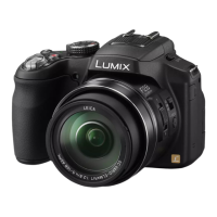
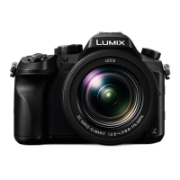
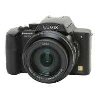
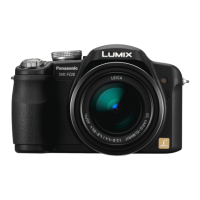
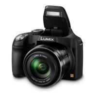
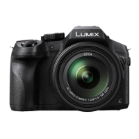
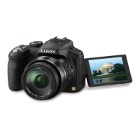
Detailed specifications for DMC-FZ200 and DMC-FZ60 models.

Location of Controls and Components

DMC-FZ200 and DMC-FZ60 Control Layouts

Diagrams and numbering of controls on both camera models.

Service Mode and Error Codes

Error Code Memory and Display

Description of the error code memory function and how to display it.

Error Code List and Exit Procedure

Detailed error code list and how to exit the display mode.

Service Tools and Procedures

Service Fixtures, Tools, and PCB Replacement

List of tools, fixtures, and procedures for PCB replacement.

Disassembly and Assembly Instructions

Disassembly Flow Chart and PCB Locations

Overview of disassembly steps and PCB locations.

Detailed Component Disassembly

Step-by-step instructions for disassembling various camera parts.

Lens Disassembly Procedure

Lens Component Removal Steps

Detailed steps for disassembling lens flex, master flange, zoom motor, and lens frames.

MOS Unit Removal and Adjustment

Instructions for removing the MOS unit and required optical tilt adjustment.

Measurements and Adjustments

Pre-Disassembly Checks and Flash-ROM Backup

Initial setting release and flash-ROM backup procedures before disassembly.

Electrical Adjustment Procedures and Specifications

Steps for electrical adjustments, including specifications and finalization.

Post-Adjustment Initial Setting

Procedure for re-setting the camera after adjustments before shipping.

Maintenance

Cleaning Optical and Display Surfaces

Guidelines for cleaning the lens, viewfinder, and LCD panel.

Block Diagrams

System, VideoAudio, LensFlash, and Power Diagrams

Comprehensive block diagrams of camera systems.

Wiring Connection Diagram

Interconnection Diagram

Diagram showing the interconnection of various units and PCBs.

Schematic Diagram Notes

Safety Notices and Diagram Conventions

Safety notices and explanations of schematic diagram symbols and indications.

Parts List Notes

Parts Ordering and Safety Information

Notes on ordering parts, safety precautions, and ESD standards.

Related product manuals