52
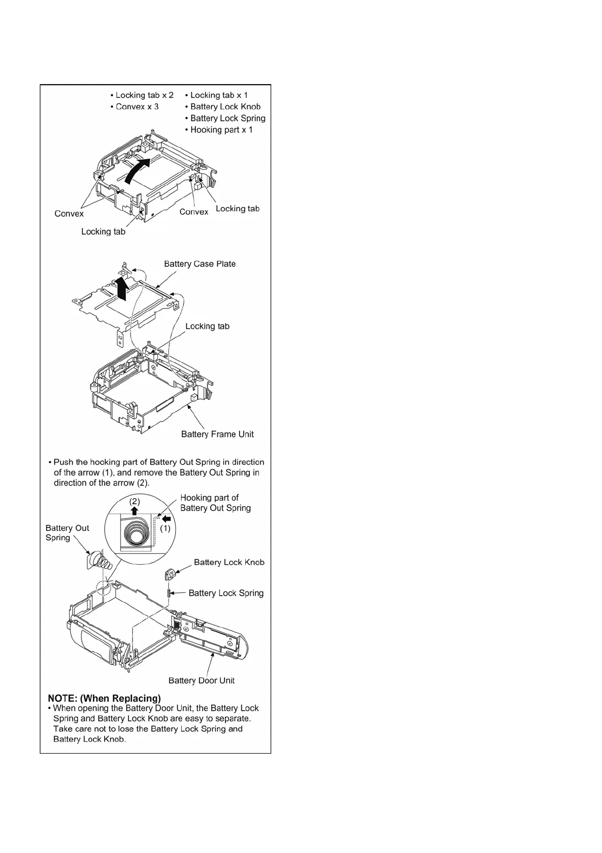
9.1.3.14. Removal of the Battery Case Plate
and Battery Out Spring
(Fig. D26)
NOTE: (When Installing)
Make sure to confirm the following points when installing:
• The Screw is tightened enough.
• Installing conditions are fine. (No distortion, no abnormal-
space.)
• No dust and/or dirt on image sensor surface. (live mos)
• LCD image is fine. (No dust and/or dirt on it, and no gradient
images.)
9.2. Disassembly and Assembly
Procedure for the Lens
Please refer to the following service manuals about Disassem-
bly and Assembly of bundled lenses.
• H-FS12032PP/E/GK: Order No.DSC1311036CE
• H-X015PP/E/GK: Order No.DSC1405015CE
• H-FS35100PP/E/GK: Order No.DSC1410024CE

 Loading...