Do you have a question about the Panasonic Lumix DMC-GM5KP and is the answer not in the manual?
Important safety notices, guidelines, and procedures for leakage current testing.
Techniques to prevent damage to sensitive components from static electricity.
Procedures for replacing, recycling, and handling lithium-ion batteries safely.
Safety guidelines and wiring information for the AC power cord and plug.
Overview of the manual and references for servicing bundled lenses.
Critical information for servicing specific units like Front-Mount, Main P.C.B., Venus Engine.
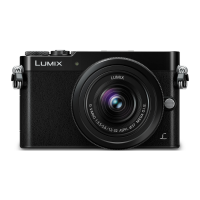
Technical specifications for the DMC-GM5 camera body, including power, sensor, and features.
Technical specifications for interchangeable lenses: H-FS12032, H-FS35100, H-X015.
Identification and function of buttons, dials, and indicators on the camera body.
Identification of parts and controls on the interchangeable lens units.
How to access, display, and interpret error codes stored in the camera's memory.
Procedures for inspecting camera body and lens operation before determining defects.
Procedures to check the Wi-Fi circuit and remove password protection.
List of specialized fixtures, tools, and cleaning kits required for servicing.
Requirements for clean work areas and adjustment notes after Main P.C.B. replacement.
Guidelines for using extension cables for servicing in specific positions.
Flow charts and location diagrams for disassembling the camera body.
Step-by-step instructions for disassembling various camera body parts.
Step-by-step instructions for removing the camera's rear case unit.
Step-by-step instructions for removing the camera's LCD unit.
Step-by-step instructions for removing the camera's Main Printed Circuit Board.
Step-by-step instructions for removing the camera mount and lens ring.
Instructions for removing the front grip sheets on both sides of the camera.
Instructions for removing the top case unit and front side plate/strap holder.
Instructions for removing the battery and top Printed Circuit Boards.
Step-by-step instructions for removing the microphone flexible print circuit (FPC).
Instructions for removing the Live View Finder unit and module.
Instructions for removing the battery unit and battery door unit.
Instructions for removing battery case plate and references for lens disassembly.
Chart mapping replaced parts to necessary adjustments and inspections.
Guidelines for cleaning the camera body, image sensor, and lenses.
Comprehensive diagram of the camera's system architecture and component connections.
Block diagrams detailing the video and audio processing circuitry (Part 1 & 2).
Block diagram showing the lens interface and hot shoe circuitry.
Block diagram illustrating the camera's power supply and regulation system.
Diagram showing electrical connections between various units and components.
| Camera Type | Mirrorless |
|---|---|
| Sensor Type | Live MOS |
| Sensor Size | Four Thirds |
| Image Processor | Venus Engine |
| Lens Mount | Micro Four Thirds |
| Continuous Shooting | 5.8 fps |
| Focus Points | 23 |
| Viewfinder Type | Electronic |
| Viewfinder Resolution | 1, 166, 000 dots |
| Built-in Flash | Yes |
| External Flash Support | Yes |
| Storage Media | SD/SDHC/SDXC |
| Connectivity | Wi-Fi |
| Battery | DMW-BLH7 |
| Weight | 211 g (body only) |
| Effective Pixels | 16.0 MP |
| ISO Sensitivity | 200-25600 |
| Shutter Speed | 1/16000 - 60 sec |
| LCD Screen Size | 3.0 inches |
| LCD Screen | Tilting |
| Video Recording | Full HD 1080p at 60/50/30/25/24 fps |
| Battery Life | Approx. 220 shots (CIPA standard) |