Fig. 15
Printed board
Upper body
Fig. 16
Fig. 17
Fig. 18
Cord reel Assembly
Motor unit Lower body
Remove
connection
Remove
connection
Fig. 19
Noise suppressorMotor
Rear motor
support
Front motor
support
Fig. 20
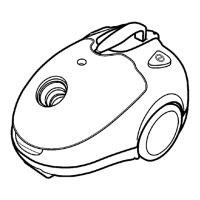
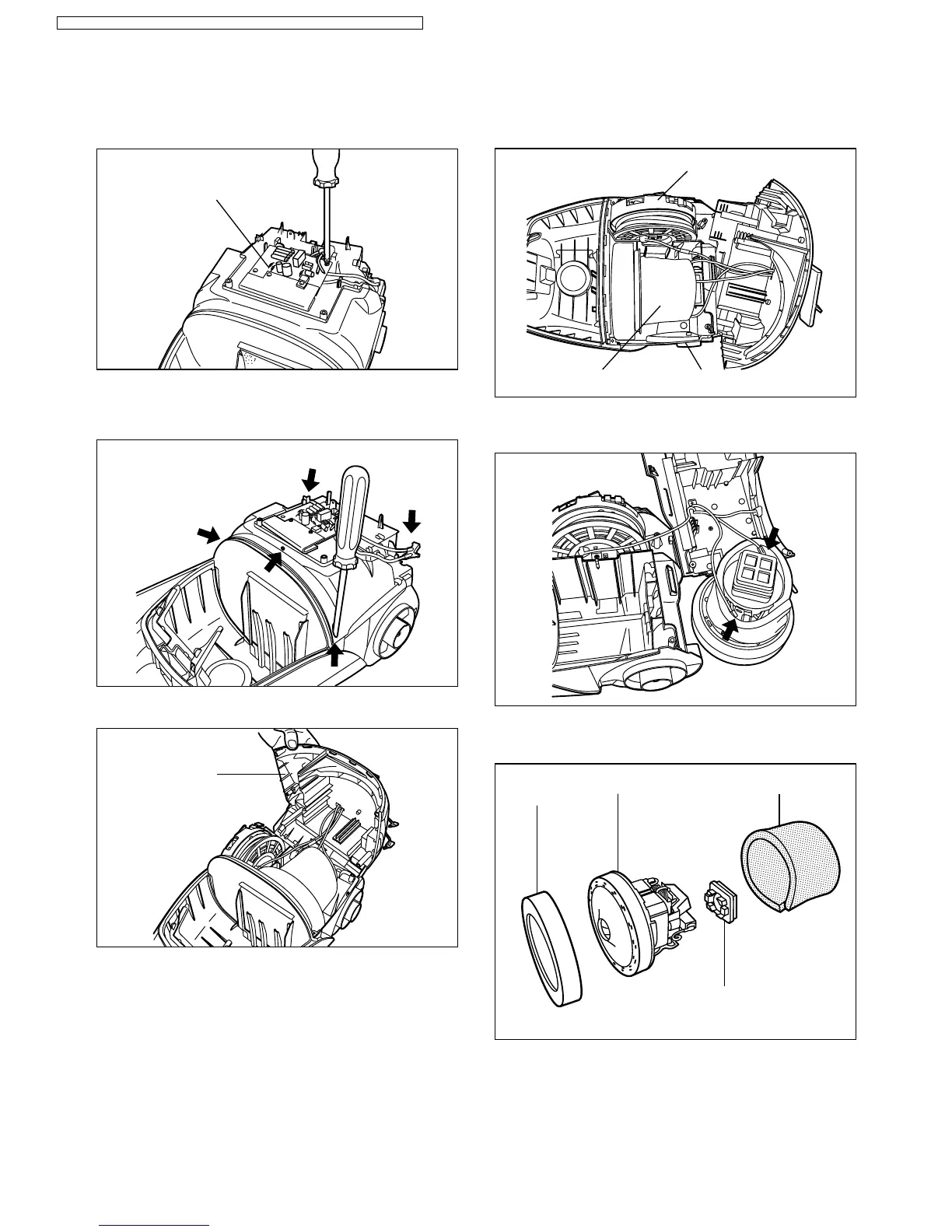
5.7. Removing upper body
1. Remove the printed circuit board fastening screws
(2 pieces), and float the circuit.(Fig. 15)
2. Remove the lower body seal.
3. Remove the upper body fastening screws (5 pieces)
at the arrowed position. (Fig. 16)
4. Remove upper body. (Fig. 17)
5.8. Replacing motor
1. Straightly pull up the motor unit from the lower body
for replacing. (Fig. 18)
2. Disconnect faston connection terminal from the motor.
(Fig. 19)
3. Remove front / rear motor support and noise suppressor.
(Fig. 20)
4. Replace motor unit with a new one.
11
MC-E7305 / MC-E7305K / MC-E7303 / MC-E7303K / MC-E7302 / MC-E7301 / MC-E7301K