WWW.100Y.COM.TW WWW.100Y.COM.TW WWW.100Y.COM.TW
WWW.100Y.COM.TW WWW.100Y.COM.TW WWW.100Y.COM.TW
WWW.100Y.COM.TW WWW.100Y.COM.TW WWW.100Y.COM.TW
WWW.100Y.COM.TW WWW.100Y.COM.TW WWW.100Y.COM.TW
WWW.100Y.COM.TW WWW.100Y.COM.TW WWW.100Y.COM.TW
WWW.100Y.COM.TW WWW.100Y.COM.TW WWW.100Y.COM.TW
WWW.100Y.COM.TW WWW.100Y.COM.TW WWW.100Y.COM.TW
WWW.100Y.COM.TW WWW.100Y.COM.TW WWW.100Y.COM.TW
WWW.100Y.COM.TW WWW.100Y.COM.TW WWW.100Y.COM.TW
WWW.100Y.COM.TW WWW.100Y.COM.TW WWW.100Y.COM.TW
WWW.100Y.COM.TW WWW.100Y.COM.TW WWW.100Y.COM.TW
WWW.100Y.COM.TW WWW.100Y.COM.TW WWW.100Y.COM.TW
WWW.100Y.COM.TW WWW.100Y.COM.TW WWW.100Y.COM.TW
WWW.100Y.COM.TW WWW.100Y.COM.TW WWW.100Y.COM.TW
WWW.100Y.COM.TW WWW.100Y.COM.TW WWW.100Y.COM.TW
WWW.100Y.COM.TW WWW.100Y.COM.TW WWW.100Y.COM.TW
WWW.100Y.COM.TW WWW.100Y.COM.TW WWW.100Y.COM.TW
WWW.100Y.COM.TW WWW.100Y.COM.TW WWW.100Y.COM.TW
WWW.100Y.COM.TW WWW.100Y.COM.TW WWW.100Y.COM.TW
WWW.100Y.COM.TW WWW.100Y.COM.TW WWW.100Y.COM.TW
WWW.100Y.COM.TW WWW.100Y.COM.TW WWW.100Y.COM.TW
WWW.100Y.COM.TW WWW.100Y.COM.TW WWW.100Y.COM.TW
WWW.100Y.COM.TW WWW.100Y.COM.TW WWW.100Y.COM.TW
WWW.100Y.COM.TW WWW.100Y.COM.TW WWW.100Y.COM.TW
WWW.100Y.COM.TW WWW.100Y.COM.TW WWW.100Y.COM.TW
WWW.100Y.COM.TW WWW.100Y.COM.TW WWW.100Y.COM.TW
WWW.100Y.COM.TW WWW.100Y.COM.TW WWW.100Y.COM.TW
WWW.100Y.COM.TW WWW.100Y.COM.TW WWW.100Y.COM.TW
WWW.100Y.COM.TW WWW.100Y.COM.TW WWW.100Y.COM.TW
WWW.100Y.COM.TW WWW.100Y.COM.TW WWW.100Y.COM.TW
WWW.100Y.COM.TW WWW.100Y.COM.TW WWW.100Y.COM.TW
WWW.100Y.COM.TW WWW.100Y.COM.TW WWW.100Y.COM.TW
WWW.100Y.COM.TW WWW.100Y.COM.TW WWW.100Y.COM.TW
WWW.100Y.COM.TW WWW.100Y.COM.TW WWW.100Y.COM.TW
WWW.100Y.COM.TW WWW.100Y.COM.TW WWW.100Y.COM.TW
WWW.100Y.COM.TW WWW.100Y.COM.TW WWW.100Y.COM.TW
WWW.100Y.COM.TW WWW.100Y.COM.TW WWW.100Y.COM.TW
WWW.100Y.COM.TW WWW.100Y.COM.TW WWW.100Y.COM.TW
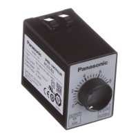
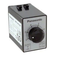
Speed controller
* Please read your User's manual carefully so that you will understand the operation and safety precautions before attempting to operate the system.
C-13
Speed controller Brake Unit Options Index
EX type
Speed controller
* Please read your User's manual carefully so that you will understand the operation and safety precautions before attempting to operate the system.
C-12
Wiring of cooling fan motor (F) or motor with thermal protector (TP)
5
<Precautions>
1. The thermal protector (TP) is an automatic reset type. To prevent hazards caused by restarting, connect
the TP as shown above. Don’t connect TP directly to the power supply.
2. Once the TP operates, cooling period is required before the operation can restart.
3. Connect the cooling fan motor (F) across pins 1 and 2 on the power terminal.
4. Motor (M) and tachometer generator (TG) should be connected according to corresponding wiring
diagram shown later.
Wiring to electromagnetic brake (40 W or smaller)
6
<Precautions>
1. Operate SW9 simultaneously with RUN/STOP switching of other switches, if any.
Placing other switch to RUN position while the brake is active (SW9 at STOP position) causes the motor
to generate heat.
2. For remaining wirings, refer to corresponding wiring diagram.
Wiring diagram (for unidirectional rotation)
7
• Variable speed motor with electromagnetic
brake should be wired as shown below.
• The thick continuous lines represent main circuit. Use conductor of size 0.75 mm
2
or larger for the main line.
• The thin continuous lines represent signal circuit. Use conductor of size 0.3 mm
2
or larger in the signal circuit.
When the distance from the tachometer generator (TG) is long, use shielded twisted pair cable.
Used to set the number
of revolutions.
1/4 W, 20 kW, taper B
Capacitor
(supplied with motor)
Motor
CW
White
Gray
Black
Pink
Pink
TG
• Soft-start/down control
• Maximum speed control
• Operation changeover switch
2
1
8
7
6
5
4
3
DIN terminal block
AT7803
Matsushita Electric
Works, Ltd.
(extra-cost option)
Power
supply
Power switch
(extra-cost option)
External speed changer (VR)
(supplied with the controller)
SW A Momentary N.O. contact
SW B Momentary N.C. contact
Relay
100 V supply system 125 VAC 5 A or more 3a contact
Ry
200 V supply system 250 VAC 5 A or more 3a contact
2
1
TG
TG(Pink)
TP Blue
TP Blue
F(Black)
TP
M
Black
White
Gray
Rated voltage
input
Ry
Ry
F(Black)
SW A
SW B
Ry
ClosedClosed
Opened
Run
SWB
ONON ON
Ry
SWA
TP
Closed
Closed
Closed Closed Closed
Pin No.
Ry Relay
F
Speed controller
Speed controller
Reset
2
1
Pin No.
STOP
C1
Yellow
Yellow
Motor
Brake
Rated voltage
input
R1
RUN
SW9
Spark killer
SW1
SW9
Spark killer R1+C1 DV0P008 (option)
100 V supply system 5 A or more at 125 VAC
200 V supply system 5 A or more at 250 VAC
Soft-start and soft-down times can
be adjusted by a single setting.
Use this feature to protect the load
from shock caused by sharp speed
change at startup and shutdown of
the motor.
To disable the soft operation, turn
the control fully clockwise.
Use this control to adjust the
revolving speed when the external
speed changer is set at the top
speed.
Adjust the speed to 1400 (min
–1
) or
below at 50 Hz; or 1700 (min
–1
) or
below at 60 Hz.
Select “high-stable” or “high-
response”:
<High-stable>
• Keeps the rotation speed variation
low against variation in load.
• Enables a wide range of speed
control.
• Suitable for capability control.
• May fail to maintain constant
rotation speed upon sharp load
change.
<High-response>
• Enables quick response with low
hunting.
• Suitable for positioning
application.
• May fail to keep rotation speed
variation low against variation in
load.
• Not suitable for controlling wide
range of speed.
NFB
SW1
NFB
Ground the return circuit to the earth terminal.
(100 Ω or less, ø1.6 mm or more).
Tightening torque: 1.0 to 1.5 N·m
Circuit breaker (NFB)
: 5A
<Caution>
Install a ground-fault
circuit interrupter in
the power supply.
 Loading...