EasyManua.ls Logo

Panasonic GM1 Series - User Manual

Panasonic GM1 Series
138 pages
Print Icon
To Next Page IconTo Next Page
Loading...
Motion Controller
GM1 Controller EtherCAT
User’s Manual
Setup Edition
WUME-GM1ETCSU-01
2021.8

Table of Contents

Other manuals for Panasonic GM1 Series

Questions and Answers

  • J
    jenniferhicksAug 20, 2025
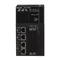
    What to do if the motor doesn't turn on Panasonic Controller and the LED is flashing?
    • J
      josefosterAug 20, 2025
      If the motor of your Panasonic Controller doesn't turn and the LED for pulse output A or B is flashing or lit, ensure the servo is on using the PG_Power function block. Also, verify that the driver's power supply is on, the wiring between the pulse output unit and the driver is correctly connected, the 24 V DC voltage is supplied to the external power supply terminals (A20 and B20), and the pulse output method settings are appropriate for the driver.
  • S
    schneiderleahAug 21, 2025
    Why is the rotation direction reversed on my Panasonic Controller?
    • S
      Spencer CruzAug 22, 2025
      If the rotation or movement direction of your Panasonic Controller is reversed, ensure the wiring between the pulse output unit and the driver is correctly connected. Check that the CW / CCW output or the Pulse / Sign output has been connected to the pertinent input on the driver side. Verify that the command position of the function block is correctly specified. Specify the Pulse / Sign output and CW / CCW output using the GM Programmer. If the settings for the position command data have been designed with the plus (+) and minus (-) directions reversed, change the direction of rotation using the parameter.
  • L
    Laura MccormickAug 25, 2025
    What to do if a limit error occurs on Panasonic GM1 Controller?
    • A
      andreacookAug 25, 2025
      If a limit error occurs with your Panasonic Controller, use the PG_ReadStatus function block to check if the over limit switch is ON. If the over limit switch is OFF or there isn't one, change the limit input logic using the parameter. If the over limit switch is ON, clear the error status using the PG_ClearError function block. Execute either JOG operation or home return to move the table until the over limit switch goes OFF.
  • D
    donaldsonjamieAug 26, 2025
    How to troubleshoot motor not turning on Panasonic GM1 Controller when LED is off?
    • J
      james08Aug 27, 2025
      If the motor of your Panasonic Controller doesn't turn and the LED for pulse output A or B is not lit, review the program. Also, check the input logic of the over limit switch; in this case, the error LED is lit.
  • S
    Sharon CampbellAug 28, 2025
    Why doesn't the speed slow down during home return on my Panasonic GM1 Controller?
    • C
      Carol RussellAug 28, 2025
      If the speed doesn't slow down for a home return on your Panasonic Controller, it's possible the near home input hasn't been read correctly. Forcibly turn the near home input switch ON and OFF from an external source, and check if the near home input display LED 'D' on the pulse output unit lights. Check if the input valid logic for the near home input switch is normally either ON or OFF. Also, check the parameter for home return. As a default, the near home input is set to 'NO contact'. When the near home input is not connected, the unit processes as the near home input is invalid.
  • M
    Morgan HunterAug 29, 2025
    What to do if Panasonic Controller movement doesn't stop at home position?
    • K
      kimberlycarsonAug 30, 2025
      If the movement does not stop at the home position after decelerating for home return on your Panasonic Controller, it's possible that the PG_Home has not been executed correctly. Forcibly turn the home input sensor ON and OFF from an external source, and check to see if the home input display LED 'Z' on the pulse output unit lights. Check to see if the input valid logic for the home input is normally either ON or OFF. Check the parameter for home return. As a default, the home input is set to 'NC contact'. When the home input is not connected, the unit processes as the home input is invalid.
  • K
    Kevin BrooksSep 1, 2025
    Why is the stopping position off during home return on my Panasonic GM1?
    • T
      Troy RyanSep 1, 2025
      If the stopping position is off for a Home Return on your Panasonic Controller, shift the position of the near home input switch in the direction of the home return to the position in the opposite direction. Also, correct the program and set the home return speed to a slower speed.
  • C
    Christina CordovaSep 3, 2025
    What to do if the Pulse Output Unit ERROR LED is lit on Panasonic GM1?
    • D
      David AdamsSep 3, 2025
      If the Pulse Output Unit ERROR LED lights on your Panasonic Controller, an over limit error has occurred. Check the ErrorId output of the function block.
  • J
    Joseph SchmittSep 5, 2025
    What to do if the ERROR LED flashes on the Panasonic Controller?
    • L
      landrychristopherSep 5, 2025
      If the ERROR LED is flashing, it indicates a self-diagnostic error. Here’s how to check the condition: 1. On the GM Programmer, select Online>Status to check the error code. 2. Switch to STOP mode. 3. On the Status screen, check the error information. For operation continue errors, try RTEX Reset / Error Clear. 4. Address the situation according to the specific error code.
  • S
    Sydney OrozcoSep 7, 2025
    Why is the ALARM LED lit on my Panasonic GM1?
    • M
      Michelle WhiteSep 7, 2025
      The ALARM LED indicates that the system watchdog timer has been activated, stopping the Controller's operation. To resolve this: 1. Set the control unit to STOP mode and restart the power supply. If the ALARM LED lights up again, the unit might have a problem. If it goes out, noise might be the cause. 2. Check the surrounding environment for noise interference, including the wiring and installation. Ensure wiring to the control unit isn't too close to power lines and that necessary shield processing has been performed.

Summary

Before Using This Product

Safety Precautions

Explains important rules to prevent personal injury and property damage.

Restrictions on the GM1 Controller and Servo Amplifiers

Basic Operations of the GM1 Controller

Power ON

Describes the correct power-on sequence for the system including the GM1 Controller.

Operation Mode Switching

Explains how to switch between RUN and STOP modes for the GM1 Controller.

Installation and System Setup

Overview of the GM Programmer

Overview of PANATERM Lite for GM

Parameter Window

Details how to check, rewrite, and save servo amplifier parameters.

Object Window

Explains how to display and edit objects on the amplifier side.

Monitor Window

Describes how to view operating states of servo amplifiers and I/O signals.

Alarm Window

Allows users to check error and warning statuses of the servo amplifier.

Preparing for Servo Amplifiers

Initial Setup for Servo Amplifiers

Provides steps for the initial setup of servo amplifiers before connecting to the system.

Connecting the GM1 Controller and Servo Amplifiers

Setting an Address for Each Servo Amplifier

Explains methods for setting addresses for servo amplifiers via EtherCAT.

Connecting the GM1 Controller and the GM Programmer

Communication Setting

Details how to configure communication settings for LAN and USB ports.

Commissioning

Details the online config mode and conducting commissioning for servo amplifiers.

Setting up Connected Servo Amplifiers

Preparation for Operation

Checking Safety Circuit Design

Covers safety circuit design and installation, including over limit switches.

Operation Check

Describes how to check network, input signals, and movement directions.

Panasonic GM1 Series Specifications

General IconGeneral
TypeProgrammable Logic Controller (PLC)
Output TypeRelay, Transistor
Number of Inputs8
Number of Outputs6
Programming LanguageLadder Diagram
Communication PortsRS232, RS485
Memory Capacity8KB
Operating Temperature0-55°C

Related product manuals