EasyManua.ls Logo

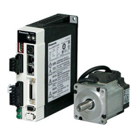
Panasonic Minas A4 Series - User Manual

Panasonic Minas A4 Series
366 pages
To Next Page IconTo Next Page
Loading...
RGB ELEKTRONIKA AGACIAK CIACIEK
SPÓŁKA JAWNA
Jana Dlugosza 2-6 Street
51-162 Wrocław
Poland
biuro@rgbelektronika.pl
+48 71 325 15 05
www.rgbautomatyka.pl
www.rgbelektronika.pl
DATASHEET
www.rgbautomatyka.pl
www.rgbelektronika.pl
OTHER SYMBOLS:
MCDDT3520
PANASONIC

Table of Contents

Other manuals for Panasonic Minas A4 Series

Questions and Answers:

Panasonic Minas A4 Series Specifications

General IconGeneral
Pollution Degree2
Control ModeTorque, Speed, Position
CommunicationRS-485
Control MethodPWM control
Protection FunctionsOvercurrent, Overvoltage, Overload, Overheat, Encoder error
Operating Ambient Temperature0°C to 55°C (non-freezing)
Storage Temperature-20°C to 65°C
Cooling MethodNatural Cooling or Forced Air Cooling
WeightVaries by model (e.g., 0.6 kg, 0.8 kg, 1.2 kg, etc.)
Ambient Humidity90% RH or less (non-condensing)

Summary

[Before Using the Products]

Safety Precautions

Essential instructions to avoid machinery damage and operator injury during operation.

Maintenance and Inspection

Guidelines for routine maintenance and periodic inspection of the driver and motor.

Introduction

Overview of the MINAS-A4 Series AC servo drivers and motors, their features, and intended use.

Parts Description

Detailed description of the driver, motor, and console components and their functions.

[Preparation]

System Configuration and Wiring

Guidance on overall wiring, main circuit connections, and peripheral equipment connections.

Timing Chart

Illustrates the timing sequences for AC power-ON, command input, and driver actions.

Setup of Parameter and Mode

Describes the function and purpose of various parameters for setting up driver characteristics.

How to Use the Front Panel and Console

Instructions for operating the driver using the front panel or the optional console.

[Connection and Setup of Position Control Mode]

Control Block Diagram of Position Control Mode

Visual representation of the signal flow and components in position control mode.

Wiring to the Connector, CN X5

Detailed information on connecting signals and pins to the CN X5 connector.

Trial Run (JOG Run) at Position Control Mode

Procedures for performing a trial run without connecting to a host controller like PLC.

Real-Time Auto-Gain Tuning

Explains how the driver automatically estimates load inertia and sets optimum gains.

Parameter Setup

Lists and describes parameters for functional selection and gain/filter adjustments.

[Connection and Setup of Velocity Control Mode]

Control Block Diagram of Velocity Control Mode

Diagram illustrating the signal flow and components for velocity control.

Wiring to the Connector, CN X5

Detailed information on connecting signals and pins to the CN X5 connector for velocity control.

Trial Run (JOG Run) at Velocity Control Mode

Steps for performing a trial run in velocity control mode without a host controller.

Real-Time Auto-Gain Tuning

Guidance on automatic gain tuning for optimizing performance based on load inertia.

Parameter Setup

Details parameters for functional selection, gain/filter adjustments, and auto-gain tuning.

[Connection and Setup of Torque Control Mode]

Control Block Diagram of Torque Control Mode

Diagram showing the signal flow and components for torque control.

Wiring to the Connector, CN X5

Instructions for wiring signals and pins to the CN X5 connector for torque control.

Trial Run (JOG Run) at Torque Control Mode

Steps for conducting a trial run in torque control mode without external host connection.

Real-Time Auto-Gain Tuning

Explanation of how to perform real-time auto-gain tuning for torque control.

Parameter Setup

Overview of parameters for functional selection, gain/filter adjustments, and auto-gain tuning.

[Full-Closed Control Mode]

Outline of Full-Closed Control

Explanation of the full-closed control concept and its benefits for high-precision positioning.

Control Block Diagram of Full-Closed Control Mode

Diagram illustrating the system configuration for full-closed control mode.

Wiring to the Connector, CN X5

Detailed wiring examples for connecting signals and pins to the CN X5 connector.

Connection to the Connector, CN X7

Instructions for connecting the external scale to the CN X7 connector.

Real-Time Auto-Gain Tuning

Guidance on performing real-time auto-gain tuning within the full-closed control mode.

Parameter Setup

Lists parameters related to functional selection and adjustments for full-closed control.

[Adjustment]

Gain Adjustment

Procedures for manual gain adjustment to optimize machine performance and response.

Real-Time Auto-Gain Tuning

Steps to perform real-time auto-gain tuning for automatic stiffness setup and gain optimization.

Fit-Gain Function

Explains the Fit-Gain function for automatic stiffness setup during position control.

Adaptive Filter

Details on how the adaptive filter estimates and reduces resonance vibration.

Manual Auto-Gain Tuning (Basic)

Guides for manual gain tuning through front panel, console, or PANATERM® software.

[When in Trouble]

When in Trouble

Troubleshooting guide covering general checks, protective functions, and error codes.

Troubleshooting

Lists common issues like motor not running, unstable rotation, and positioning errors with causes and measures.

[Supplement]

Absolute System

Information on setting up an absolute system using absolute encoders and host controller communication.

Communication

Details on connecting to the driver/NC via RS232 and RS485 for parameter management and monitoring.

Dimensions (Driver)

Physical dimensions of the driver for different frames (A, B, C, D, E, F).

Dimensions (Motor)

Physical dimensions and specifications for various motor series.

Motor Characteristics (S-T Characteristics)

Provides S-T characteristic curves for various motor series under different conditions.

Motor with Gear Reducer

Details the combination of drivers and motors with gear reducers, including part numbers.

Permissible Load at Output Shaft

Specifies the permissible radial and thrust loads on the motor shaft for different models.

Related product manuals